Bought a few QCTPs to compare quality in inexpensive brands.

Good question.

I've been thinking about this for the last 2 hours. I like being challenged - it helps me to discover what assumptions I work with.


You have in interesting point there, and I'll try to address it also.


well said.

Let me go into some detail here: All really top-of-the-line tool posts use multiple techniques to prevent movement of the tool post. Unfortunately Aloris and Aloris-style tool posts don't. Look they are good - I have one.

View attachment 445892

The force on the tool post can result in rotation, and also translation - movement across the face of the compound rest. In a typical Aloris style QCTP the only way to resist rotation is by friction from the tension of the bolt and the surface area in grey. The other movement can in part be controlled by the fit of the t nut by having friction on the red dotted line as well as the geometry of the bolt itself. By only having .020 between the T nut and the bottom of the tool post, there is a strong structure created where bending of the bolt is far more difficult. any strong force will then try to slide the T nut into the red dotted line. There is an unavoidable component of force going down the length of the T slot, but the far greater forces act on the grey area and the red dotted line.

What happens if the T nut is not tight fitting? You lose the firm seat for the end of the bolt, or seen another way, gives another surface that can slip - that is the underside of the compound-to top of the T nut connection. For less than an hour's work, you can eliminate this potential slipping surface.
Excellent description. The same forces are at play where the compound mounts to the cross slide. Thus, it's best to keep the tool post centered over the position where cross slide attaches to the compound. This is a particular weakness of mid-sized (10-14") lathe compounds - the further you have the tool post cantilevered out via the cross slide, the more the tool will deflect downward under load, and the more twisting torque is applied to the entire tool mounting setup. Especially true when performing parting operations.
 
Am I correct in my recolection that the T-nut is also prefered to be the total width of the compound slot? Similar reasoning. More clamping area and stability?

What limits the width of your toolpost T-nut is how you position your post in practice. I've never met a lathe that I could run with the toolpost dead center on the compound. It doesn't matter if you like your compound at 29 degrees or true 90, in order to maintain prudent stickout length and reach the work, usually the toolpost has to be slid along the T-slot channel to a good position. If the T-nut were the full length of the compound, it would stick out of the T-slot and into the work space. So I make my T-nuts the width of the toolpost so I can slide it flush with the side of the compound facing the work and still get 100% contact between the post and compound.
 
Am I correct in my recolection that the T-nut is also prefered to be the total width of the compound slot? Similar reasoning. More clamping area and stability?
it is the way i do it. looks nicer, too....
 
After reading the very knowledgeable posts above and thinking about the rotational forces involved I think that there are at least two design flaws in the typical commercial tool posts.

First the flat bottom of these tool posts have nothing to prevent rotation and rely entirely on fiction between the bottom of the tool post and the top of the compound to prevent rotation. The above discussions about having perfectly mated surfaces are nothing more than a work around to solve the design flaw. The simple solution to this is to have a tab on the bottom of the tool post that fits into the slot on the compound. This would prevent the tool post from rotating to change the angle of the tool bit to the work. On my 4 way there are indents in the base to allow it to be rotated in 15* increments. These tool posts cost a lot of $$$$. Why should the user have to live with a design flaw when such simple solutions exists. There is a tab on the bottom of my norman that fits into the slot. Problem solved.

The other design flaw is how far the tool bit is held from the center of the tool post. The further the tool bit is held from the center of rotation the greater this force is. I don't have a commercial tool post to measure. On my norman the center of a 3/8 HSS tool bit is .875 from the center of rotation. The commercial tool posts look to be much greater than this.

The other flex issue is the post moving back or forward. My guess is this is not an issue with the commercial tool posts because they rest on the top of the compound. Any movement would have to come from the compound, cross slide or carriage. This could be an issue with my norman. I will try to measure this possible deflection the next time I use my lathe.
 
Interesting mental exercise.
The proof is in the pudding. Has anyone done comparative measurements to see how much deflection there is?
I've never had an observable defection or result that I know of.
There are lots of possible areas of deflection besides the tool post. Each area needs to be evaluated separately to find the culprit.
I have a BAX Chinese wedge type, on a Chinese 1440 lathe with 3 hp & import tool holders. The T-bolts that hold the compound to the dross slide would also seem to be a potential source of movement.
I'm lazy and almost always in a hurry to get the bulk of the metal gone. The result is taking fairly deep cuts but not at high rotational speeds.
I keep the compound back and locked. A good tug on the tool post handle & on the 6"+- lever that holds the tool post to the Tee nut in the compound slot. I adjust the tool post angle as needed and quite often. Angle of the compound doesn't matter a lot, as I never use the 29.999° angle for threading. I've got tools from 1/4" HSS to inserted carbide 5/8". I minimize stick-put when getting aggressive.
Since I don't (think) I have any defection problems I'll keep blundering along making more serious mistakes. Got other things to worry about.
 
Interesting mental exercise.
The proof is in the pudding. Has anyone done comparative measurements to see how much deflection there is?
Since I don't (think) I have any defection problems I'll keep blundering along making more serious mistakes. Got other things to worry about.
I tend to agree.
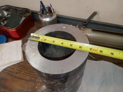
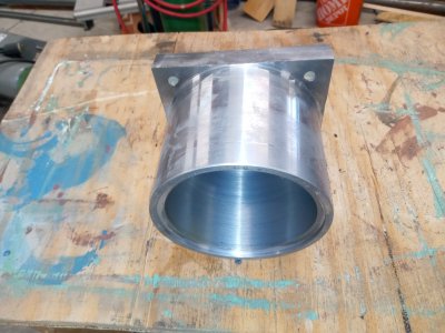
I had to bore nearly an inch out of the ID.
CXA Aloris.
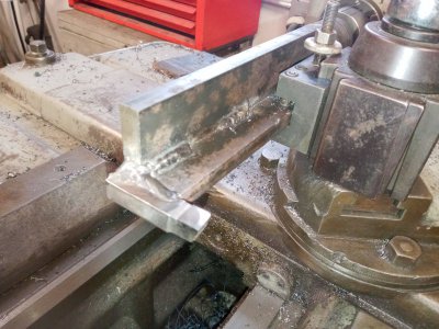
My crude, home made boring bar.
I didn't baby it.
Deflection?
Nothing causes more deflection than a boring bar taking heavy cuts.
Take light cuts when you get down near your finish size and you're good.
 

Attachments

  • 20230215_185444.jpg
    20230215_185444.jpg
    314.5 KB · Views: 17
  • 20230220_152004.jpg
    20230220_152004.jpg
    533.2 KB · Views: 17
  • 20230226_141602.jpg
    20230226_141602.jpg
    383.1 KB · Views: 17
First the flat bottom of these tool posts have nothing to prevent rotation and rely entirely on fiction between the bottom of the tool post and the top of the compound to prevent rotation.
This is certainly not true of Dorian and Aloris QCTP systems, and I presume some of their clones. Both Dorian and Aloris QCTP's are provisioned with anti-rotation dowel-pin holes in the bottom, and shipped with the dowels as shown below:

Dorian QCTP.jpg

Those dowel pins are VERY effective anti-rotation devices when mated with a matching hole in the T-nut that secures the QCTP to the compound (pointed to in the following photo):

QCTP on Compound.jpg

95 percent of the time, I have the QCTP mounted to a solid tool post plinth that replaces the compound. You can see in the following photos how the anti-rotation pins are implemented for this setup.

Solid Tool Post Plinth.jpg

Dorian Anti-Rotation Pins.jpg

Solid.jpg

This setup has improved rigidity immensely and also eliminated any tendency, even with the compound, for the tool post to rotate under load. I've documented this design, including detailed drawings at this link if anyone is interested. @Jake P, amont others, has implemented the same system on his PM-1440 which is thoroughly documented in this thread. It really makes a huge difference in rigidity.
 
After reading the very knowledgeable posts above and thinking about the rotational forces involved I think that there are at least two design flaws in the typical commercial tool posts.

This is certainly not true of Dorian and Aloris QCTP systems, and I presume some of their clones. Both Dorian and Aloris QCTP's are provisioned with anti-rotation dowel-pin holes in the bottom, and shipped with the dowels as shown below:
My real Aloris does not have reamed holes for dowels, but it is a good thing to do. Project #457,961.

Dickson tool posts have a reamed dowel hole top-to-bottom, as a locating and anti-rotation feature. you loosen the nut, pull the pin and rotate.

Emco ?Enco? I always get them confused -- has 24 ball bearings that accurately locate their Dickson, 4-way and their Aloris clones. the locking plate is machined to be a tight fit to the dovetail (by the installer/user). This allows 15 degree rotation increments... I have 2 of these posts, and they are the very high end posts IMO...

That is why I made the slightly combatant comment about anti-rotation features in my post above.
 
My real Aloris does not have reamed holes for dowels, but it is a good thing to do. Project #457,961.
Interesting. I've worked with at least 3 others on a solid plinth for their genuine Aloris QCTP's and they all have a single dowel pin hole as shown in the following drawing. Maybe it was added or removed since you bought yours. If the QCTP doesn't already have such a dowel pin hole, it's easy enough to add one (or several).

Aloris BXA QCTP.jpg
 
My real Aloris does not have reamed holes for dowels, but it is a good thing to do. Project #457,961.

Dickson tool posts have a reamed dowel hole top-to-bottom, as a locating and anti-rotation feature. you loosen the nut, pull the pin and rotate.

Emco ?Enco? I always get them confused -- has 24 ball bearings that accurately locate their Dickson, 4-way and their Aloris clones. the locking plate is machined to be a tight fit to the dovetail (by the installer/user). This allows 15 degree rotation increments... I have 2 of these posts, and they are the very high end posts IMO...

That is why I made the slightly combatant comment about anti-rotation features in my post above.
And I'm wondering what in the heck he is machining that he needs that level of rigidity...
 
Back
Top