-
Welcome back Guest! Did you know you can mentor other members here at H-M? If not, please check out our Relaunch of Hobby Machinist Mentoring Program!
You are using an out of date browser. It may not display this or other websites correctly.
You should upgrade or use an alternative browser.
You should upgrade or use an alternative browser.
Bd920n Reversing Issue
- Thread starter boostin53
- Start date
- Joined
- Sep 11, 2015
- Messages
- 293
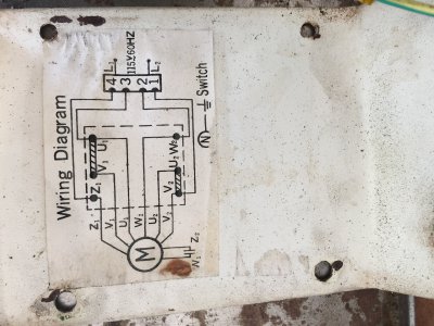
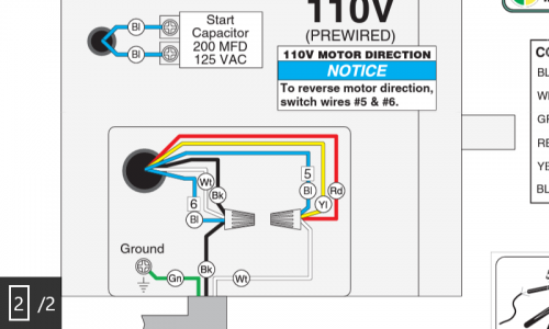
Would the blue wire be the same as the grey wire on my motor? And honestly, that diagram doesnt do me any good. Im no good at wiring electronics. I need this brokendown to me like this, "hey dumb ass, switch these wires here and put those there" or something of that nature.
- Joined
- Sep 11, 2015
- Messages
- 293
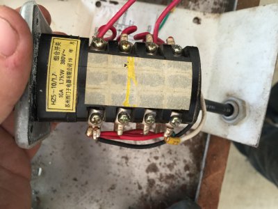
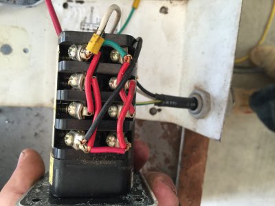
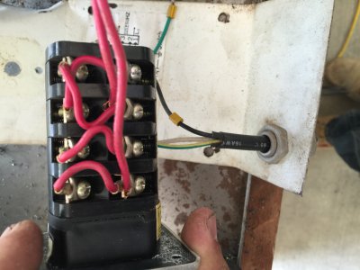
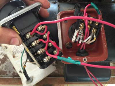
I believe the problem is the switch wiring. I traced the wires in both the forward and reverse settings. In the reverse position, both lines to the motor receive power from the black wire and its jumper. Its the cross over thats messing me up. Im not sure how to get them to change. I googled a bunch and its not making sense to me. I cant find diagrams to switches similar to this one and how it works.
- Joined
- Jan 16, 2015
- Messages
- 26
Sorry I've been driving all day, so it's difficult to respond. The blue wire in the diagram are from the run capacitor. Check what color wires you have coming off the capacitor. The diagram will make more sense if you isolate those wires.
- Joined
- Sep 11, 2015
- Messages
- 293
Sorry I've been driving all day, so it's difficult to respond. The blue wire in the diagram are from the run capacitor. Check what color wires you have coming off the capacitor. The diagram will make more sense if you isolate those wires.
The motor is wired correctly up to the switch according to the diagram. Its the wiring on the switch thats giving me a problem. It runs forward, but doesnt run at all when switched to reverse. I believe its how the cross over is wired, its wrong. I trace the wires while in reverse mode and i end up with black on both wires to the motor. And idont know how to wire it correctly.
- Joined
- Sep 28, 2013
- Messages
- 4,395
do you have a digital multimeter? If so, you should be able to figure out which are the terminals that are switched from forward to reverse. My guess would be the 4 center poles on the switch. There are a bunch of switch wiring diagrams out there on the net - find one that suits your motor (115V capacitor start?) and wire your switch accordingly. I understand how split phase motors are wired (the start windings are reversed to change direction) but I've no idea about yours. Also, I really don't understand the wiring plate on your lathe - 2 of the wires should be swapped when wiring it CW vs. CCW but both the schematics look the same!
- Joined
- Sep 11, 2015
- Messages
- 293
Keep in mind i dont know much at all about these kind of things. But the switch has two layers of contacts to flow power. When looking from the top, with the screws facing you, forward position closes the bottom layer of contacts on both sides of the switch. When in reverse position, the top layer of contacts close and the bottom contacts open. Like i said, the motor spons forward like normal, but doesnt do anything when switched to reverse. This is seriously frustrating the crap out of me. I know when i figure it out, im going to feel so stupid.
- Joined
- Dec 8, 2013
- Messages
- 2,651
It appears in your photos that your line cord goes to the switch and then only two wires go from the switch to the motor. Is that true? If so you won't get reverse no matter what you do at the switch.

