Basic CNC

the motor can turn 3000 rpm you just would not have any power out of it at that speed
my new motor said that also, they are set to 100ipm and with my screws that is 500 rpm they work fine.
if i took the screw loose and let the motor free rev and set mach to 600 ipm they would spin 3000 but i could probably stop it with my fingers
they can do it but for what reason? there is not time for them to reach full current per pulse/step so they have no power
steve
 
I still question it Steve. I'm a little apprehensive. If you tighten to get to zero the closer you get the slower it will rotate. I may be out in left field here with this oine.

"Billy G" :thinking:

if I put 3 hardened parallels in a vise with a ball on each side of the center one and closed the screw until there was no play/backlash i could pull the center one out with out any problem because the balls would roll, they dont need play to roll to an area the same size they were in. put the parallels together without the balls tighten the exact same amount and nothing could be moved.
steve
 
Question --- In a screw thread some backlash has to be present. Zero backlash on a screw thread equals zero movement. Is this the same with a ballscrew. I see many advertized as "Zero Backlash". Is it really "zero"

"Billy G" :thinking:

There is a trick to this, and it depends on how the anti-backlash scheme is implemented. Also, it is "Zero backlash for certain values of zero".

First off, there are 3 common ways for implementing anti backlash on a ballscrew

1) Oversized balls

This involves loading the ball nut with balls that are slightly too large. The nut is forced to expand outward (and the screw slightly inward) because as always, somethings gotta give. This creates a load against all 4 contact points (2 on the nut, 2 on the screw) for each ball. This is the cheapest solution, and works really well, but is not adjustable for wear

2) Double nut, sprung

This is probably the second most common method. It involves 2 ball nuts, and a spring loaded spacer. The spacer forces the nuts apart, forcing one nut against the right side of the screw threads, and one nut against the left side of the screw threads. This can be used with lower quality screws because the spring loaded spacer allows for compliance when faced with inaccuracies in the screw pitch. It also adjusts for wear. The main trick here is that the load on your nut cannot exceed the spring load of the spacer.

3) Double nut, rigid

This involves using two ball-nuts, separated by an adjustable spacer. The spacer is adjusted to remove all play. Basically, one nut is pressing on the left side of the screw threads, and the other is pressing on the right side of the screw threads. This is the best, and most expensive solution, but requires a very accurate ($$$$) screw because variations in the screw pitch will cause variations in load on the rigidly mounted nuts. This type is adjustable for wear.

So, remember I said "for various values of zero"? Most assemblies that I have seen (that actually listed this value) show real backlash on the order of one tenth. I think we can all agree, that is pretty good, but not "zero". With a precision ground screw and a double nut, rigid mount, you could no doubt do better, but that arrangement would likely cost more than all the equipment in my shop currently..

The other thing to realize is that ballscrews and nuts, being made out of real, actual STUFF, behave like really stiff springs. If you push on them hard enough, they will move. The more the load, the more the stretch. you never get rid of it all, but you can minimize it by going to larger screws.

The other thing to realize is that these special nuts only work to a certain load, after you have defeated your pre-load (in the case of the overside ball, and double-nut arrangement), you are back in backlash country.

To address Bill Gruby's concern regarding too much force on the screw when eliminating backlash, realize that these are not sliding members. Just like setting a pre-load on a bearing (think wheel hubs), you _are_ going to increase the force required to move the bearing proportional to the pre-load, but the force required to turn a rolling element assembly is so low to begin with that the resultant force is still _really_ low.

This brings up the issue of "self" feeding. It turns out that the friction on ballscrews is so low that when you remove power from the motors, and nothing is holding them, the force of gravity can be enough to move them (think z axis). sometimes people add brakes to stop this when power is removed.
 
Last edited:
While still on motors Steve suggested we discuss Holding Torque compares to Running Torque. This is past my knowledge so we will wait for someone else to explain it.

"Billy G" :))
 
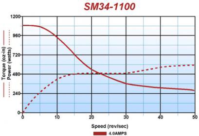
holding torque is the advertised torque of the motor sitting still, and it is used to determine use but there are differences in motors. as soon as the motor starts to turn this torque starts going down.without knowing the pulse rate and speed you will be running the motor the manufacturer cannot tell you the torque it will produce running.
the chart i posted shows a nema34 1100 oz/in motor at different speeds they are not showing pulse rate so i can only assume they are showing full step because that is the highest torgue output setting running (and they want to sell motors ). if you double the pulse (half step) you cut torque almost in half for these figures.
note that this motor at 50 revolutions per second, thats 3000 rpm is only rated at 250 oz/in.
so if you think about using a smaller motor and gearing it down to increase torque are you really doing anything
lets say we have this 1100 motor but we need 2200 torque to do the work it has to do at 100 inches per minute rapids
to start we need to know the speed we need to work with for our use so lets say - for 100 inches per minute feed rate with a 5 threads per inch screw we need 500 rpm.
so at 500 rpm from the motor we are at about 960oz/in but we need 2200 oz in
so we go to a 2 to 1 ratio to double torque, now we need 1000 rpm for 100ipm and our torque is about 1280 still to low
a three to one ratio, 1500 rpm for 100ipm and our torque is about 1260
the only way to do this and raise torque is to reduce desired speed by as much as half or more.
so before you purchase pulleys and a belt see what the bigger motor costs if you want any speed left
if your project has to have higher speeds you can only get there with a bigger motor turning slower
I'm sure i made a mistake somewhere but its all based on ideal not real world and that would make all this worse.
you have to click the image to see it the software is not displaying gif files in the thread
steve

stepper-motor-sm34-1100-curve.jpg
 
OK folks. Let's move on to the "Driver". It's up to you guys now. I'm in the dark too.

"Billy G":dunno:
 
the driver is in the basic way of thinking is just an amplifier if converts the low voltage signal (pulses) from the pc into a voltage and current the motor needs to move. as far as microstepping that is a mystery to me how it gets the motor to stop between the poles except it changes polarity constantly freezing the motor in place. and how all this is done is way over my head.
steve
 
Looks like we could use a little help here guys. Anybody up for it?

"Billy G" :))
 
The driver explanation works for me. This thread is titled 'basic' cnc, and following the 'basic' theme, I feel that while for instance it may be interesting to know how microstepping is accomplished, I'm more concerned to know why it's needed.

Likewise I'm more I'm more concerned to know the pros and cons of the differing ways to wire the motors to the driver board, and how to position the dip switches, than I am in how the components of the driver board actually work, interesting though that might be.

I think some discussion on the choice of driver boards, power supplies, breakout boards and the any number of auxiliary boards that are available (take a look at the products from http://www.cnc4pc.com/Store/osc/index.php for example, specifically a 'charge pump'; I'll bet it isn't what you think it might be!), would be useful to anyone just starting into CNC.

I think most people here are mechanically inclined, so the choice and physical installation of the motors, couplers, maybe ballscrews, shouldn't be any great challenge, but identification of the most suitable electronic components and perhaps the software, may come less naturally to some of us, me included.


M
 
Back
Top