Atlas milling machine refresh project

Since you just happen to have your headstock all apart, could you measure the eccentrics on the backgear shaft and post the meanurements? I need to make a new pair, but was going to "wing it", due to missing measuruments & originals.
 
Very nice work! Makes me feel like I should tear down my MFB and repaint it. My MF1 power feed gear box case broke at the mounting flange to the knee. Mine had the same dried up, caked on grease. Soaking in lacquer thinner got it cleaned out. My power feed engagement lever was really stiff which probably was the cause of the gear box breaking off in the first place. I ground the peened area off the back of the sliding shaft, removed the ball/spring for the detent. The spring got replaced with a much lower pressure spring which seems to do the trick. Mine was missing the MF16 yoke so I made one out of aluminum. I'll post some photos in a separate thread in a few.

Again, very nice work!
 
Since you just happen to have your headstock all apart, could you measure the eccentrics on the backgear shaft and post the meanurements? I need to make a new pair, but was going to "wing it", due to missing measuruments & originals.

Sure, I can do that. What measurements do you need, specifically? The front eccentric is pretty complex, as it includes the lever and eccentric all as one piece.
 
Sure, I can do that. What measurements do you need, specifically? The front eccentric is pretty complex, as it includes the lever and eccentric all as one piece.

Od of the portion that fits in the headstock, ID of the backgear shaft, and offset of the backgear shaft from center. That can be determined by measuring from the backgear shaft to the edge of the eccentric. Knowing the diameter of the shaft and the eccentric itself gives the offset.

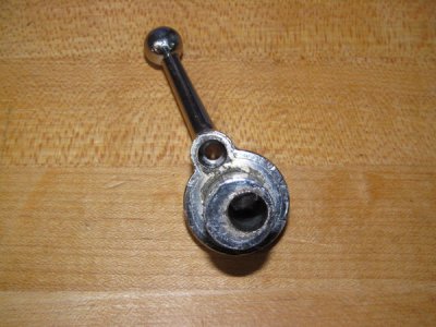
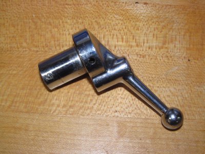
Some pictures of the front eccentric that show the handle relationship to the eccentric offset position would be helpful. I had intended to turn the front eccentric so that a shoulder stuck out the front, which would provide somewhere to mount a lever once I figured out how far it needed to rotate. Then I determine where to place a spring-loaded pin in the front eccentric shoulder to engage the locking holes on the front of the headstock. I won't be making a duplicate of the original, just a usable replacement. :)

Thanks! I appreciate it!
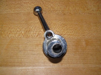
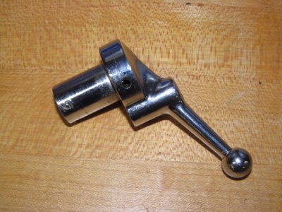
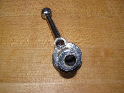
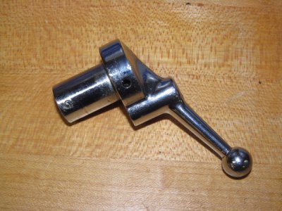
Okay -- The OD of the eccentric is .686". The shaft is 3/8" in dia. and as close as I can tell, it is offset 1/16" from the edge of the eccentric. Here are some photos of the front eccentric.

002_zpsff94f854.jpg

001_zps0b5f1536.jpg

002_zpsff94f854.jpg

001_zps0b5f1536.jpg

002_zpsff94f854.jpg

001_zps0b5f1536.jpg
 
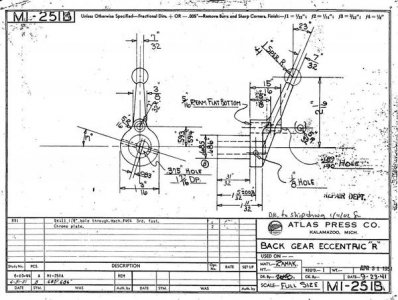
I can't vouch for the dimensions but I just uploaded a partial drawing of the front eccentric. I also don't actually know whether it matches dimensions of M1-251 or M1-251B because I don't know how they differ and won't for another few weeks.

Robert D.
 
Thank you both! That's enough useful information for me to get started looking for a suitable piece of scrap.

I'll print that drawing out and start figuring my sequence of operations.

It looks like the eccentrics are pinned to the shaft, which would make sense as Atlas liked to pin everything on these machines. 3/8" shafting I have on-hand, and I'll dig in the junk box for a suitable piece of material to make the eccentrics from. Pretty sure I have some in there somewhere.

Seems that soon we'll have three nice Atlas horizontal mills up and running!
 
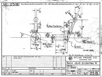
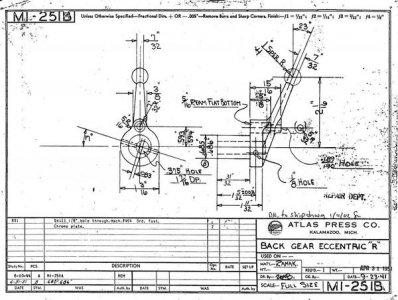
I noticed that somebody just uploaded a copy of the original Atlas blueprint drawing for this part on the Yahoo Atlas shaper and milling machine group site. It has all the dimensions you could want.

M1-251B_zps4685a0fc.jpg

M1-251B_zps4685a0fc.jpg

M1-251B_zps4685a0fc.jpg
 
Last edited:
I had intended to look and see what drawing he had uploaded. I converted the JPG to TIF, cleaned up the drawing, converted it to PDF and put in in our Downloads. I also deleted the partial drawing that I uploaded yesterday.

Robert D.
 
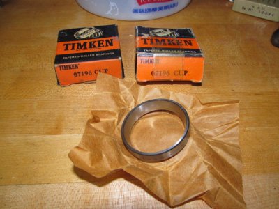
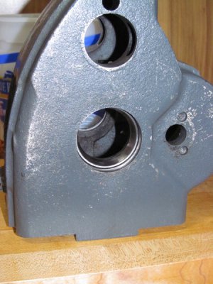
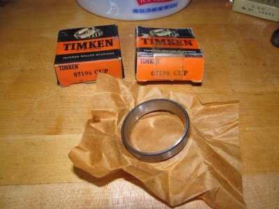
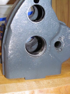
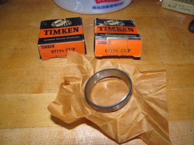
I got some goodies in the mail this week and had a chance to install them. First, I got a couple of new cups for the Timken bearings. I'm still waiting for the cones, but at least I can install these:

001_zps58dfec56.jpg


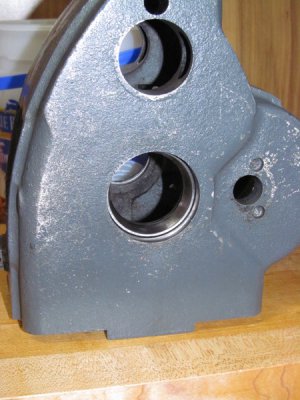
I've got both of them installed and now I'm just waiting for the other half of the bearings:

006_zps3f9ce65f.jpg

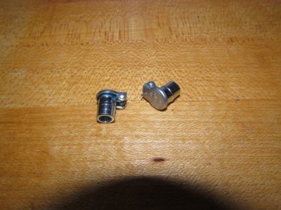
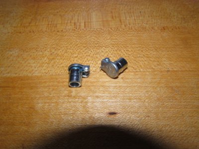
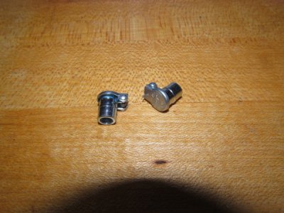
I also bought a couple of Gits oilers for the bearings. For some reason, these were missing from my mill. Somebody must have removed them at some point:

009_zps871bb428.jpg

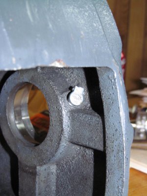
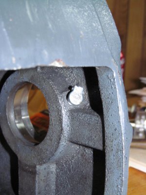
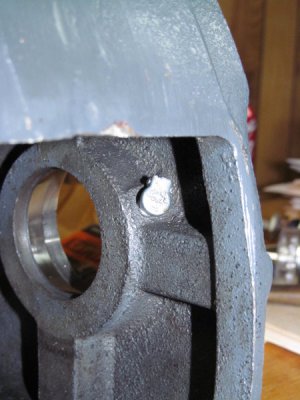
These will help keep chips and garbage out of my new bearings:

008_zps9cf6aebb.jpg

That's all for now.

001_zps58dfec56.jpg

006_zps3f9ce65f.jpg

009_zps871bb428.jpg

008_zps9cf6aebb.jpg

001_zps58dfec56.jpg

006_zps3f9ce65f.jpg

009_zps871bb428.jpg

008_zps9cf6aebb.jpg
 
Last edited:
Back
Top