Atlas Mill Followed Me Home

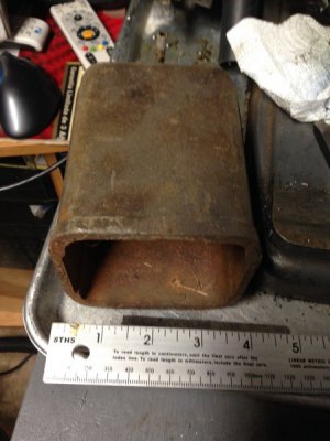
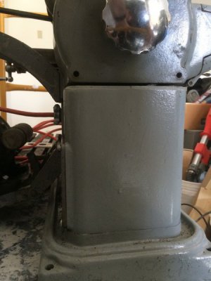
That cavity is where the pump would go. The catalogs list that cavity as having approximately 3 pints capacity. I would be inspecting for cracks and mating joints to identify possible leaks before trying to pour 3 pints of oil in there!

But while we are on the subject, as I get into cleaning up and refurbishing the grungy old MFC I acquired a couple months ago I will be looking for current day suppliers who may have a pump that can be adapted to the same task and fits in that space. I will let you know what I find, but don't anyone hold your breath. I have a long ways to go and the recent snow and cold weather here in Massachusetts is presenting a big setback.

Spiral_Chips

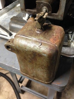
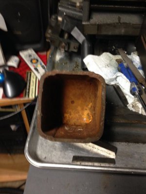
If I decide to go with coolant I will us a outside bucket for it. When I was cleaning the inside of that cavity on mine it was full of all kinds of chips. And being in the cavity it would be hard to clean out plus it is only 3 pints.
 
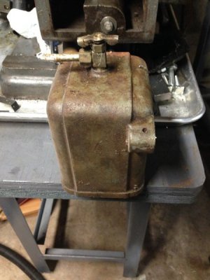
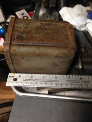
I did get the tank with my MFB mill but not the mounting bracket. The tank I have is made out of cast iron and not ZAMAK.

Cast Iron???? WoW! I confess I have never held one in my hand. I expected ZAMAK!

If I decide to go with coolant I will us a outside bucket for it. When I was cleaning the inside of that cavity on mine it was full of all kinds of chips. And being in the cavity it would be hard to clean out plus it is only 3 pints.

You make a very good point!

Spiral_Chips
 
If that's cast iron as you state, it looks like it would be a pretty simple thing to cast, and the bracket that holds it to the machine (as shown previously) looks like it would be pretty easy to fabricate as well. Am I correct in assuming this is the gravity feed, and with some tubing leading from the valve to the cutter/work piece being all that would be needed?
 
Earlier I posted a pic showing the inside of the reservoir tank that fits inside the body of the mill (the reservoir used by the internal pump, if it existed.) Here's the picture from the catalog page:
View attachment 126693
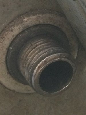
The pump is non-existent in my case. There is a threaded hole in the table where the coolant would return to the pump via the tube shown in the lower portion of the picture.
However, notice how the back panel of the machines body appears to have two tubes and a power cord coming out of it, and how it seems to have other recesses or connections which I cannot make out in the picture. That portion of my machine is blank and appears to be part of the casting. I'm not sure if a person would have to cut out the casting or if I'm missing some way that it is modified. I'm going to see if I can find out more; I may do an external reservoir like Spiral_Chips and rig up some kind of pump and leave the casting alone.
Rear Side of Casting.jpg
 
I also found some problems, but none seems like anything big:
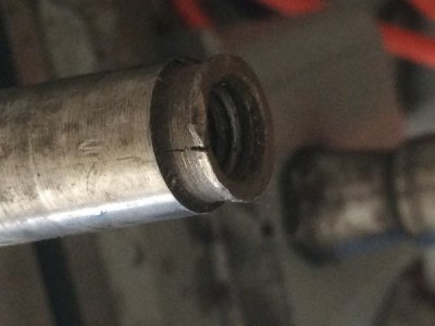
First, and worst, the internally threaded small end of the morse taper on the arbor is cracked. It kind of looks like it has been hammered on. Once I get the lathe rebuilt I intend to make a couple of arbors, so I'm not too worried. Besides, it still works!
Cracked Arbor Morse Taper (small).jpg

Next, the arbor driver is missing:
Spindle Nose, missing arbor driver (small).jpg

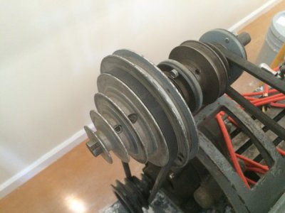
Finally, notice anything incorrect in this picture?
Pulley with 5 Sheaves (small).jpg
 
I also found some problems, but none seems like anything big:
First, and worst, the internally threaded small end of the morse taper on the arbor is cracked. It kind of looks like it has been hammered on. Once I get the lathe rebuilt I intend to make a couple of arbors, so I'm not too worried. Besides, it still works!
View attachment 126698

Next, the arbor driver is missing:
View attachment 126696

Finally, notice anything incorrect in this picture?
View attachment 126699
Am I seeing 5 steps on the upper pulley and 4 on the lower one?

Bruce
 
Back
Top