- Joined
- Feb 26, 2013
- Messages
- 128
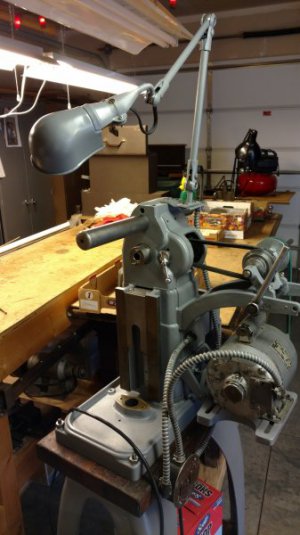
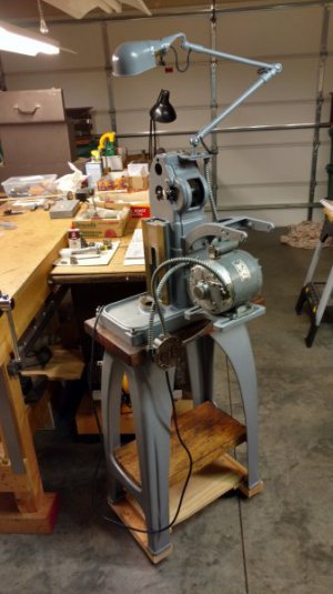
OK, so I have gathered up a few necessary parts and have a little time to get back to my project. The old saying about the journey being more important than the destination (or something like that...) comes to mind. Although I really want this project done, the research, locating parts and putting the puzzle back together has been a lot of fun. Here's a couple of pictures of where things are now. Also, Please have a look at the Back Gear question at the end, I could use a little help with this part of the assembly.
My goal here is to get the entire drive system assembled and functioning properly before I start on the rest. Here's the assembly so far-
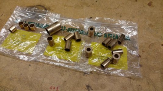
Ordered a fairly complete set of oilite bushings from McMaster Carr-
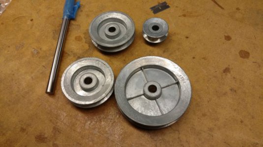
I contacted Clausing for the motor and countershaft pulleys. They had one but not the other. I decided to try to work with these zinc die cast pulleys and new shaft material, they are the same diameters as the original design. I would like to try and put together assembled pairs to replace the original double pulleys. Stay Tuned-
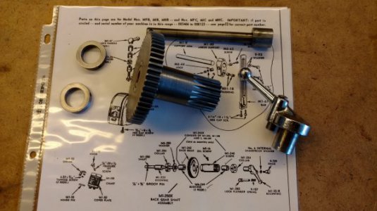
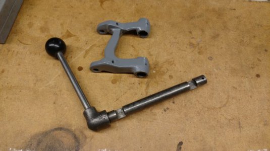
Needed a replacement and found this engage/ dis-engage lever. The milled shaft is wrong but I can make a new one. I guess it was the original cast elbow and the Bakelite knob that sucked me in-
OK, so here's where I could use a little help. I found out the back gears need to be installed before the spindle is installed. The Back Gears install easily enough but I'm not sure I have done this correctly. Please have a look and tell me what you think.
Back Gear lever in the "UP" position, Back Gears are engaged-
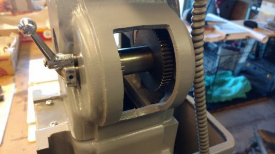
Back Gear lever in the "DOWN" position, Back Gears are dis-engaged-
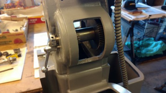
Here's the assembly with the lever all the way out-
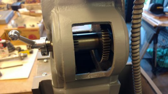
So here's where I am a bit confused, The shaft slides freely in and out and this doesn't seem right to me. I can set it in either the engage or dis-engaged position but the entire assembly is free to slide in and out by about a 1/2 inch. I am not sure if this correct, maybe it is. Any feed back on the correct way to assemble the Back Gears will be greatly appreciated, Please chime in!
Thanks for looking!
Steve
My goal here is to get the entire drive system assembled and functioning properly before I start on the rest. Here's the assembly so far-

Ordered a fairly complete set of oilite bushings from McMaster Carr-

I contacted Clausing for the motor and countershaft pulleys. They had one but not the other. I decided to try to work with these zinc die cast pulleys and new shaft material, they are the same diameters as the original design. I would like to try and put together assembled pairs to replace the original double pulleys. Stay Tuned-

Needed a replacement and found this engage/ dis-engage lever. The milled shaft is wrong but I can make a new one. I guess it was the original cast elbow and the Bakelite knob that sucked me in-

OK, so here's where I could use a little help. I found out the back gears need to be installed before the spindle is installed. The Back Gears install easily enough but I'm not sure I have done this correctly. Please have a look and tell me what you think.
Back Gear lever in the "UP" position, Back Gears are engaged-

Back Gear lever in the "DOWN" position, Back Gears are dis-engaged-

Here's the assembly with the lever all the way out-

So here's where I am a bit confused, The shaft slides freely in and out and this doesn't seem right to me. I can set it in either the engage or dis-engaged position but the entire assembly is free to slide in and out by about a 1/2 inch. I am not sure if this correct, maybe it is. Any feed back on the correct way to assemble the Back Gears will be greatly appreciated, Please chime in!
Thanks for looking!
Steve

