Atlas Horizontal mill

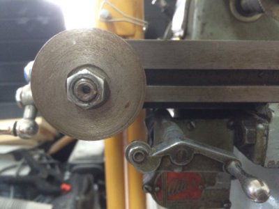
wa5cab, in the picture Steve showed of his mill with the round substitute standard kick out cam in place, it was located at the left end of the table. BUTTT... the nut on the front is to hold it in place and there is a T-nut in the front slot to hold that part in place. You can loosen it and slide the cam to any position on the slot so the cam may be located to turn the feed off whenever desired. Mine has a nut that is loosened (see picture included.)

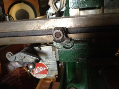
:frog:
IMG_1176.JPG
 
OK. Your photo looks more or less like the factory part. Where is Steve's photo?
 
OK. Having again looked at Steve's photos, I have no idea why I thought that the disk was attached to the feed screw.. Just pretend that I never said anything. Flustered
 
Having at least three different threads going more ore less at once brings on some "leakage" between them and results in some confusion. Unfortunately, there doesn't seem to be a simple fix for it without starting whole new threads, which come to think of it may bring even more confusion. Maybe somebody more adept than I can gather the three images (original part, Rudy's version, and the one Steve found) onto one post so we can compare them in one place.

:frog:
 
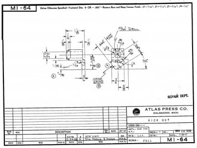
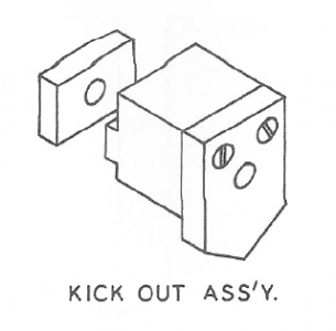
OK, this isn't the best comparison, but over the past month people have posted the Atlas drawing, Rudy's drawing, and a photo of the home made version that showed up with Steve's mill. Now let's see whether I can post them all together.

Atlas KO drawing.jpeg

That was the drawing, now let's see about the drawing from Rudy,

RudyKickOut.PNG

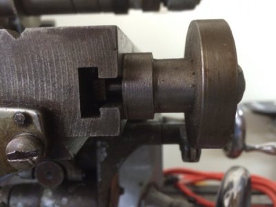
And finally, the elegantly simple version from Steve's mill (that a couple of others have tried out just since he posted it) it seems pretty simple even without a detail drawing.
Steve's H-M.jpg Steve's H-M 2.jpg

It seems that all of them do the same thing, i.e. trip the lever to turn off the table feed (as shown in Steve's picture) and that any one of them will perform their task well. It's really a simple job and not much is needed to get it done! :cool 2:

:frog:
 
Last edited:
Nice! Thank you for posting!
Steve's design does not appear to provide a way to set the kick-out point with any certain precision, but does it need to be? I am sure it will kick out at the same repeatable point on the disk as it is, but where is that point? I suppose with some testing a precise location could be figured out and marked on it, but when would one need such precision? When milling to a shoulder?

I can even see where once the kick-out point has been determined the large disk could be cut to make it more like the original or RK's version. One might be able to get more accuracy for repeatability. Actually the more I look at it the more I can see how easily this can be modified to look like the other versions. Nice work!

Spiral_Chips
 
All I did was buy the mill that had this on it. I didn't even know what it was!
 
By "modify it to look like the others" do you mean square? If you do that then you also need a shoulder on the back to keep it from rotating about its bolt. With it left as it is you can turn it without having any additional operations.
 
I copied the round version, (thanks Steve! lol) And the precise Kick-out point is right smack dab in the middle, right below the center of the bolt.
I'd imagine Rudy's version as well as the original version would also kick-out right at the lowest point. Same as the round one!

I just found the round one so easy to make. I had to try it! And I'm glad I did!
 
Last edited:
Back
Top