-
Welcome back Guest! Did you know you can mentor other members here at H-M? If not, please check out our Relaunch of Hobby Machinist Mentoring Program!
You are using an out of date browser. It may not display this or other websites correctly.
You should upgrade or use an alternative browser.
You should upgrade or use an alternative browser.
Atlas 10F V42
- Thread starter timmeh
- Start date
- Joined
- Aug 23, 2014
- Messages
- 222
The "press" frame is actually a trolley (for something about the size of a 44 gallon drum) set on it's side. You can't see them in those pic's, but on the other side of the frame are some really serious casters, rated 200kg(440lbs) each IIRC.
The pan came with the lathe, I didn't make it. I would say it's 0.5 mm(.020") thick, maybe less(not sure of gauge) galv sheet. Around 9/16" deep with a 1/8" wire bead rolled into the lip. Little rough around the edges, does the job.
I've just tidied up the sides and a few minor dents with a little panelbeating. The setup with the frame was just to put some creases in it to stiffen it up and direct oil to the centre. Same "press" from the other side.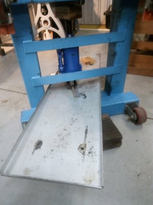 10 tonne bottle jack as ram.
The pan came with the lathe, I didn't make it. I would say it's 0.5 mm(.020") thick, maybe less(not sure of gauge) galv sheet. Around 9/16" deep with a 1/8" wire bead rolled into the lip. Little rough around the edges, does the job.
I've just tidied up the sides and a few minor dents with a little panelbeating. The setup with the frame was just to put some creases in it to stiffen it up and direct oil to the centre. Same "press" from the other side.
 10 tonne bottle jack as ram.
Last edited:
- Joined
- Aug 23, 2014
- Messages
- 222
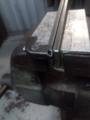
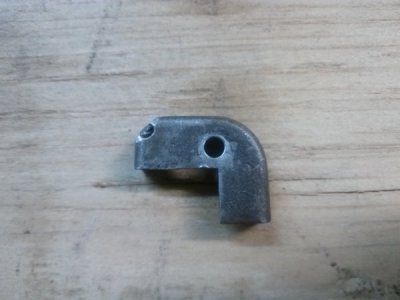
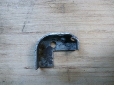
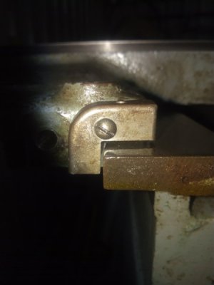
Made a few modifications to the way wipers, hopefully will allow turning full 10.250" dia. without having to remove them.
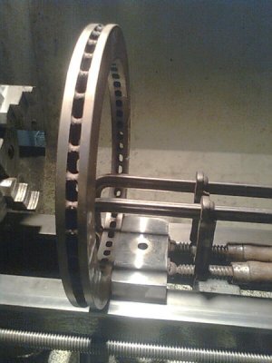
Yes, that's right, 10 + 1/4". I've started, quite some time ago now, on a fixed steady or steady rest, using an old disc rotor for the framework(pic's a bit later).
Had to file a bit of material off the chuck side "legs" of the carriage to get toolpost in close enough for trepanning/boring. Should have about 7" capacity when finished.
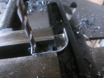
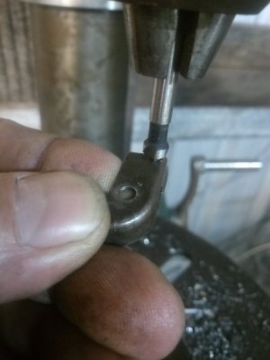
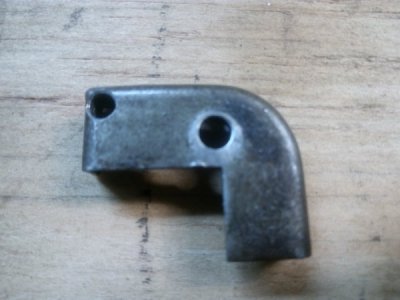
Also, some pic's of the tailstock spanner, loosely based on a flat ring spanner for an N.C. lathe I once used. Drill hole in suitably sized, spare socket. Bash in piece of bar. Bend bar.
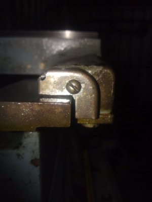
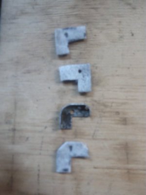
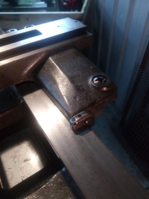
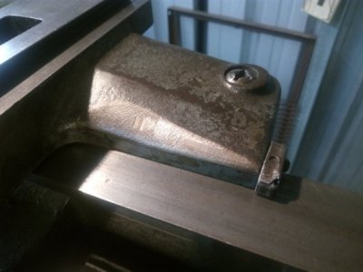
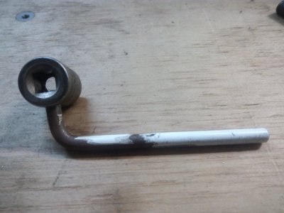
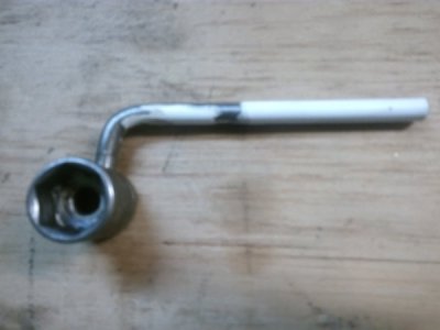
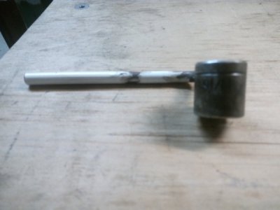


- Joined
- Aug 23, 2014
- Messages
- 222
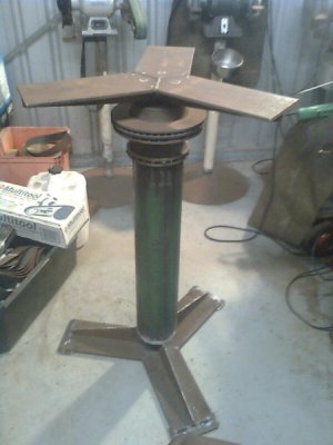
Can't seem to locate shots of the set up for the disc rotor steady. These are the finished ring(1+2), clamped to the base and then released from the chuck.
The hub section of the rotor was treppanned and used for the 3 position grinder stand(3, top of the tube/post).
The leftover ring was then bored as far as I figured prudent.
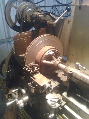
And there ya go, last shot is facing the rotor. Stumbled on this one while retrieving a shot of the grinder stand.
Will have to ponder how I went about this, been quite a while since I did it. Quick description is, face and treppan one side then the other, leaving the "ribs"? in between the rotor faces. Remove, to vice, hacksaw through "ribs". Back to lathe for clean up.
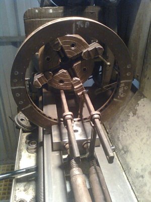


Last edited:
- Joined
- Aug 23, 2014
- Messages
- 222
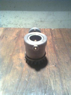
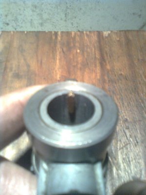
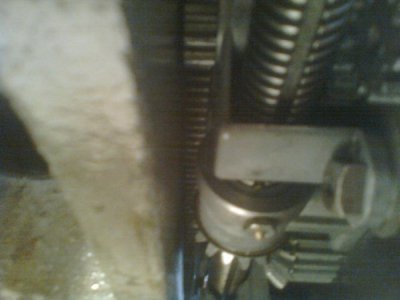
Another quick one, somewhere here recently, someone was looking at a repair/replacement for the leadscrew mitre gear.
Copied and modified from "Sons of Invention"
Brass bolt, turned and filed to fit. Also works as a sacrificial component. Tried and tested works well so far.
Pulled off up to .020" deep cuts, facing rotor in previous post. Although, that was done using the deep reduction feed rate set(a bit under .oo15").
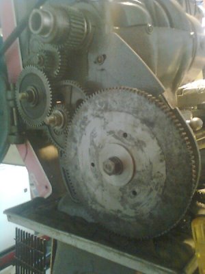
116 tooth gear... salvaged out of an old printing press.


Last edited:
- Joined
- Aug 23, 2014
- Messages
- 222
Yes, much easier than just about any other method I could find.
Did look at doing it with a steel bolt, but couldn't find one with the right sized shank(1/8" IIRC) and a decent sized head to trim down. So brass it was.
Although it would not be that difficult to make one from scratch, it would need a shear point if done in steel I think, could do considerable damage if it didn't shear cleanly in a catastrophic situation.
Another one for the "To do" pile.
- Joined
- Dec 25, 2011
- Messages
- 10,552
I don't think that I agree about the shear point. The right lead screw bearing is already the shear point. And I would guess that (although knock on wood I've never had one) almost all crashes occur during turning or threading. During which the bevel gear is not involved.
- Joined
- Aug 23, 2014
- Messages
- 222
I've seen it mentioned quite often and I think it is even stated in the atlas books that the leadscrew support bearing is intended to be a shear point.
On my machine, the compound slide was missing(a plinth in it's place), the quadrant plate had been broken and repaired, a number of change gears also missing, the Fwd/Rev gearbox input journal was bent towards the bed and down(not enough to cause a crack, enough to make meshing of gears difficult), the top left hand end of the g/box has a crack 8/10 mm long from the corner where it attaches to the bed, the tongue for the half journal at the right hand end was also bent(end of the tongue was about 5mm away from where it should have been).
Considering where I am, if the support bearing had broken, they would most likely have made a replacement. Not disputing that the bearing is the shear point, just suspect that in this case it didn't.
Secondary shear point has gotta be a good thing if it prevents further damage I figure, because I can't source parts nearby. I'd sooner have to make another "key" than have to knock up a support bearing. That reminds me of another job to do, a shear coupling on the left end of the leadscrew, like the later models.
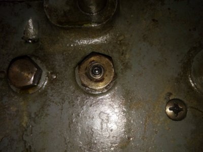
Anyway, on with the show.. Put a ball oiler in the mitre gear, and replaced all the rest.
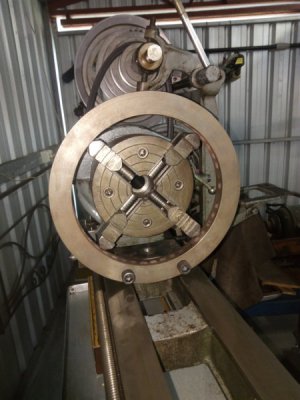
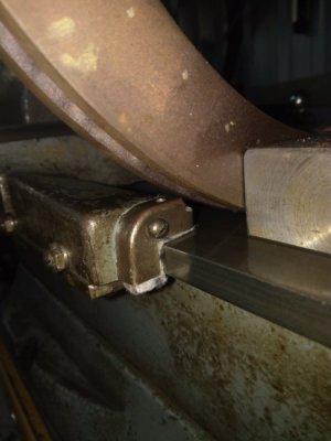
Checked fit of the steady rest after the wiper alterations, turned out spot on. Carriage needs a little more off to get in a bit closer.
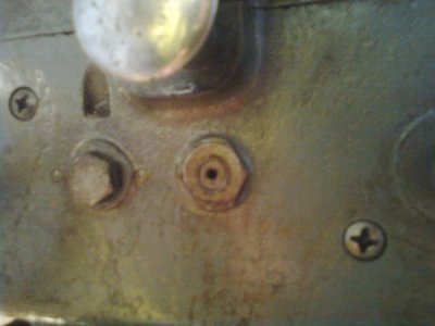
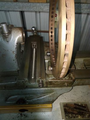
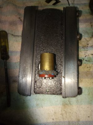
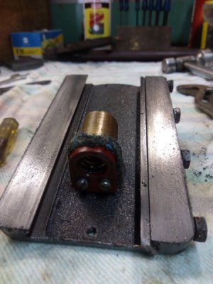
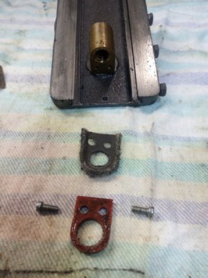
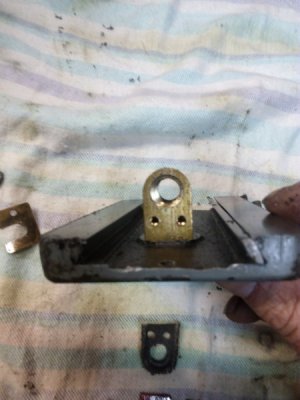
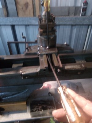
Some shots of my cross slide nut, the felt and keeper, the keeper mounting holes, and backlash adjustment,(I've not seen it done this way anywhere, in the manuals or otherwise{can anyone confirm or deny?}, was the only way i could see that helped with reducing backlash.
Coming along nicely.


Last edited:
- Joined
- Dec 25, 2011
- Messages
- 10,552
Good idea on the ball oiler. And on the cross feed screw/nut wiper. I'd suggest drilling and tapping an oil hole in line with the top of the felt. The threads would be for a plug screw to keep trash out. However, I don't understand your anti backlash comment.
And yes, a slip clutch at the left end of the lead screw would be a good idea rather than depending upon the right thrust and support bearing to break.
And yes, a slip clutch at the left end of the lead screw would be a good idea rather than depending upon the right thrust and support bearing to break.
