Another Electronic Lead Screw using the Pi Pico

That's the basic idea, but there's slightly more to it, from my understanding. But as long as you make sure that you recover the same spindle location and lead screw index (angle) it should work. Remember that the relationship between metric and imperial is not quite a simple fraction, unless I suppose you use 254/10, so you need to make sure you exactly line up, or the thread won't be exact. I haven't sat down to do the math yet - it's on my to do list.
 
That's the basic idea, but there's slightly more to it, from my understanding. But as long as you make sure that you recover the same spindle location and lead screw index (angle) it should work. Remember that the relationship between metric and imperial is not quite a simple fraction, unless I suppose you use 254/10, so you need to make sure you exactly line up, or the thread won't be exact. I haven't sat down to do the math yet - it's on my to do list.
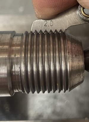
Yes, since I have an imperial lathe, metric threads ended up requiring on 5-10 times more control bits than ANSI threads. I did have to bump the maximum number of control words from 40 to 400 to support the threads I was interested in. So I don't have an issue duplicating the metric pitch with an imperial feed screw. I've proven that by cutting metric threads without disengaging the half nut.

This new approach of eliminating the thread gauge boils down to the processor being able to use the carriage position and current spindle location to know when to start driving the cartiage. A mouthful, but you're basically doing what CNC lathes already do, so it's definitely doable. I just need another state machine to handle starting the process, as I don't want interrupt latency impacting the accuracy.

I'm in the middle of something else now but when I get back on this, I'll provide the detail.
 
2mm metric thread.
My first run a few weeks ago was a scratch test. I wanted to verify that I could cut a full depth metric thread by keeping the half nut engaged, and reversing the lathe to drive the carriage back to start another cut.

Still haven't tackled the DRO version yet.
 

Attachments

  • IMG_7253.jpeg
    IMG_7253.jpeg
    227.1 KB · Views: 4
I had to add some filter caps to the wired up board to quiet the encoder signals... I had a few hundred mv of noise on every signal. The lack of a ground plane was probably a big contributor. I decided to make a PCB with a ground plane to see if I could quiet things down. I also added some additional I/O to allow for the DRO capability I'd like to add when the war department will let me get back on it.

It arrives in a week give or take. All traces with the exception of a two short ones are on the top side. the bottom is a ground plane. That should stiffen it up quite a bit (electrically that is). I have never soldered surface mount parts before (my steady handed technicians always did it :), so I wimped out and went with breakout boards for the level shifters. I've got the surface mount parts on order, and will give it a shot on a test board later on.

Screenshot 2024-04-03 at 11.39.47 PM.png
 
Back
Top