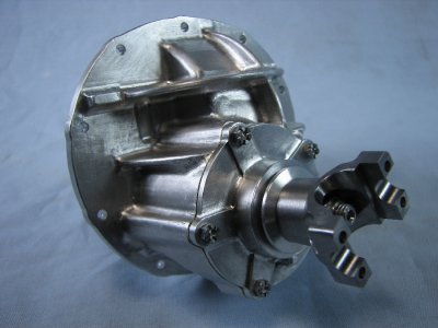
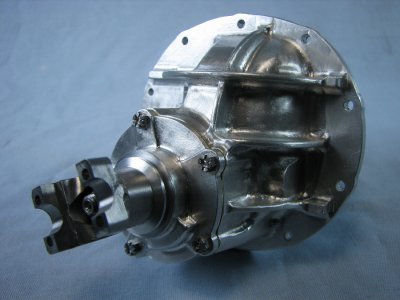
9 inch Ford differential in 1/3 scale

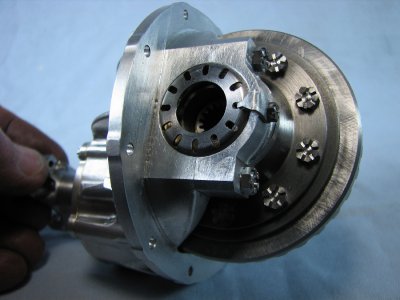
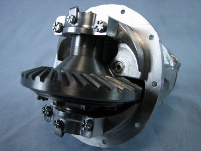
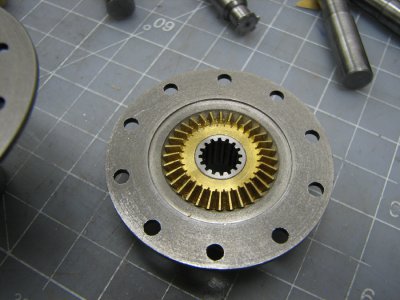
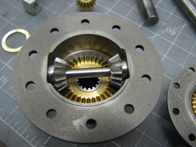
The next part would be the 2 spool halves. The spool is the part that houses the spider gears and onto which the ring gear attaches. These were mainly a turning job. There was a relief pocket cut on the inside where the spider gears fit. The spool also needed a cross reamed hole for the spider gear shaft and the tapped holes to mount the ring gear.
I had purchased a set of bevel gears that were a close fit to the required dimensions. They only came in brass and I didn't want brass against brass so I opted to make the smaller gears from steel, although with the amount of use they'll get I doubt that it would have mattered if they were all brass. I also purchased a piece of splined bushing stock. This was turned down, cut to length and pressed into the spider gears. These splined bushings will accept the ends of the axles when I get to that point.
gbritnell.
IMG_8312.JPG IMG_8309.JPG
 
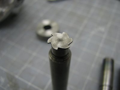
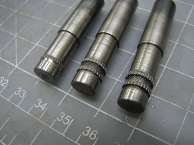
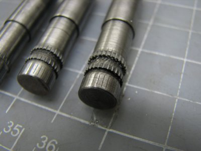
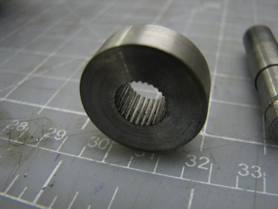
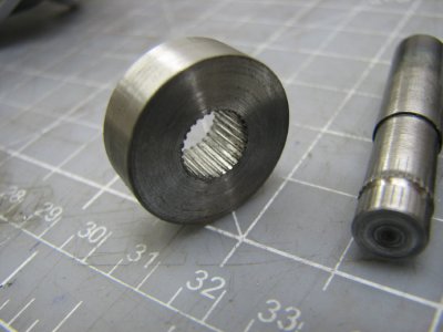
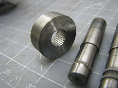
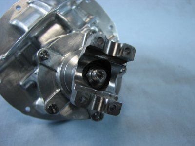
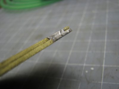
To finish up the pumpkin assembly I needed to make the driveshaft yoke. Unlike the axle spline bushings I couldn't find anything that was close to size or tooth count so I had to make my own broaches up. Having played around trying to make splines when I was working on the transmission I knew what to do and not to do. The biggest what not to do is to try and take too much material in one pass. Unlike a keyway broach when cutting splines there is so much more surface area that it takes a great amount of squeeze to get the broach through whatever part you are trying to spline. I made up 3 increasingly larger spline cutters from drill rod. Each one had a pilot that was .001 smaller than the root diameter of the spline. As the teeth got higher I left a short portion of shallower teeth so that they would easily pilot into the previous pass. Once the cutters were made I tried them out on a steel bushing as the yoke would also be made from steel. The one photo show the cutter for making the teeth on the broaches.
gbritnell

IMG_8306.JPG IMG_8288.JPG IMG_8291.JPG IMG_8295.JPG IMG_8299.JPG IMG_8302.JPG
 
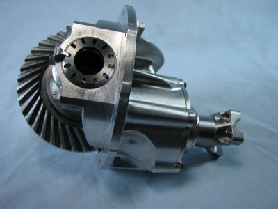
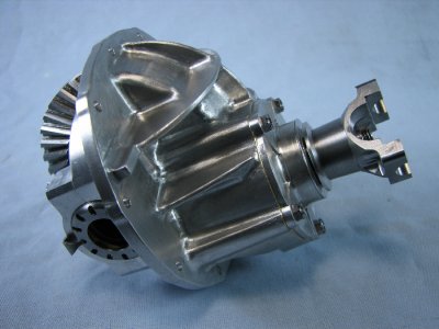
With the yoke machined and splined it was time to clean and assemble all the bits and pieces. Following are pictures of the finished pumpkin or center section.
This is a link to a short video clip.
http://youtu.be/oOkmKkvC-PE
gbritnell

IMG_8349.JPG IMG_8319.JPG IMG_8322.JPG IMG_8325.JPG IMG_8328.JPG IMG_8340.JPG IMG_8343.JPG
 
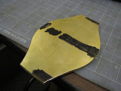
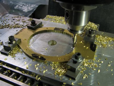
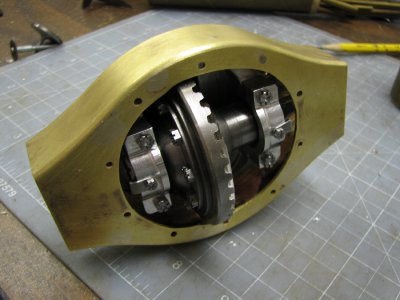
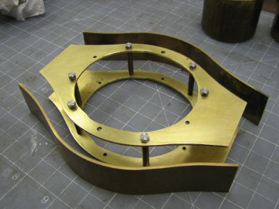
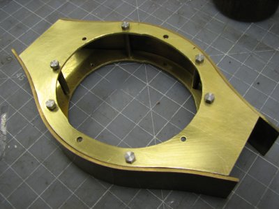
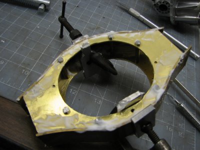
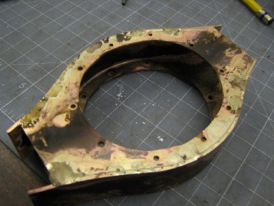
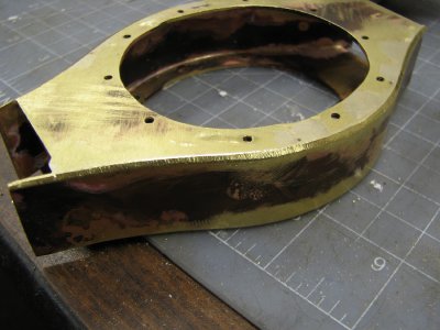
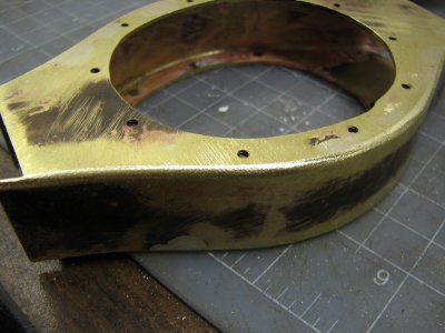
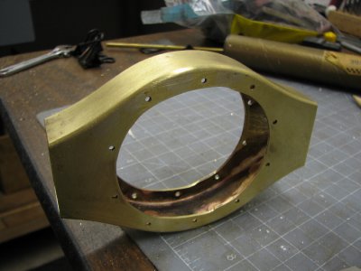
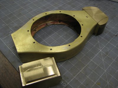
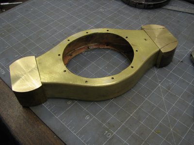
The factory banjo or axle housing is made from several pieces of stamped steel and welded together. I looked at the idea of doing something similar but for a one-off there wasn't much reason to make a set of dies. I've made dies in the past and things don't always come out like you had hoped for so I decided to fabricate the housing. Being as the housing should be painted black when finished I decided to make it from brass. I cut out the front and rear plates, soldered them together in a couple of spots and then drilled the front plate for 4-40 threads while the rear plate was opened up for clearance. This would allow me to bolt the 2 pieces together with stand-offs to maintain the width while silver soldering. The center opening was first roughed and then bumped to the layout line for finishing. The inside shape was then filed smooth and the 2 pieces were unsoldered and cleaned up.
gbritnell

- - - Updated - - -

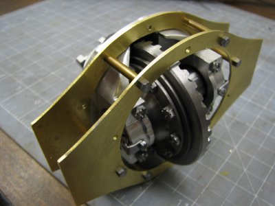
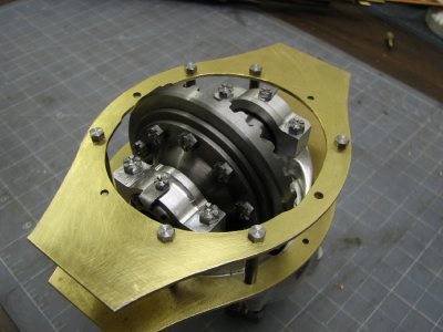
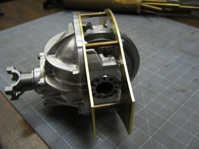
The assembled center section was then bolted to the 2 pieces to check for fit before the assembly started.
gbritnell

IMG_8383.JPG IMG_8355.JPG IMG_8358.JPG IMG_8368.JPG IMG_8372.JPG IMG_8374.JPG IMG_8377.JPG IMG_8380.JPG IMG_8397.JPG IMG_8388.JPG IMG_8395.JPG
 
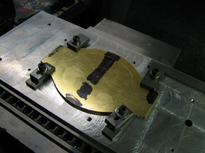
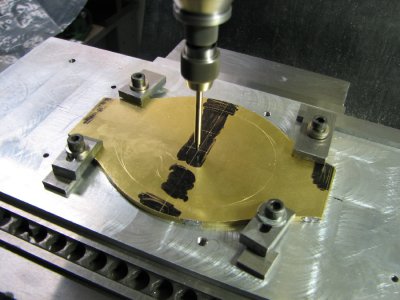
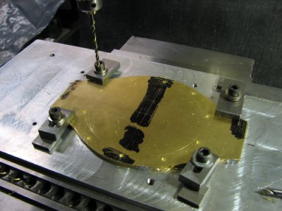
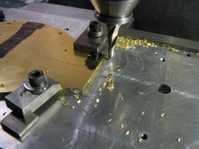
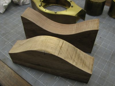
The top and bottom plates were next. I made the sides and the top and bottom from .062 brass so that I could put the proper radius on the corners without getting too thin. I made up a set of wooden bucks to form the 2 plates. They were cut a little wide, annealed and then formed. A little tweaking was necessary to get them to conform perfectly. The hardest part was trying to figure out a way to hold them in place for brazing. Everything was cleaned, fluxed and then soldered. The radii were then roughly ground with a burr and then filed and smoothed.
gbritnell

IMG_8427.JPG IMG_8400.JPG IMG_8403.JPG IMG_8407.JPG IMG_8410.JPG IMG_8413.JPG IMG_8415.JPG IMG_8419.JPG IMG_8422.JPG
 
Let me ask you this. Is this project something you are payd for or is it just your own idea?
And also are you retired or what? How come you have such amount of time for this?
 
Hi Tarmo120,
First of all, yes I am retired but a lot of my projects, 302 v-8, Holt, 4 cylinder OHV engine, etc. were done long before I retired. This is my hobby and I enjoy working on it. I don't get paid for it except in satisfaction.
gbritnell
 
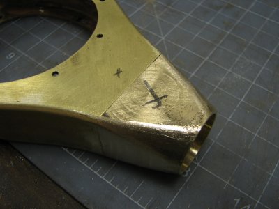
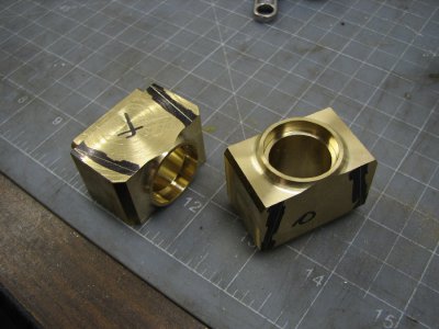
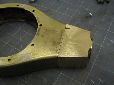
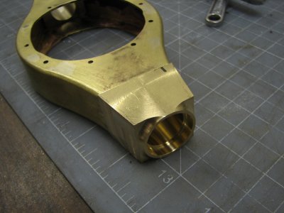
To complete the center part of the main housing I had to make the ends pieces from solid brass. The reason for this was there had to be a transition from the small radius on the housing to the full diameter where the axles tubes went in and there was virtually no way to do this from sheet brass. The pieces were cut from square stock and and chucked into the lathe to cut the through hole and counterbore for the axle tubes. A small witness was cut with a radius nosed tool so that I would have something to blend to. The other side of the blocks has a shallow recess cut so that they would insert into the already made housing. When the end pieces were finished I made up 2 bushings to go into the axle tube holes and then a through stud was inserted and nutted to hold everything in line for silver soldering. When the soldering was done I blended the 2 radii together.
gbritnell

IMG_8452.JPG IMG_8431.JPG IMG_8434.JPG IMG_8440.JPG IMG_8446.JPG IMG_8449.JPG
 
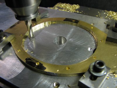
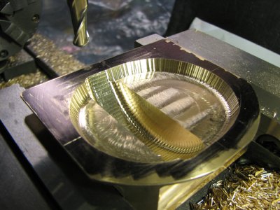
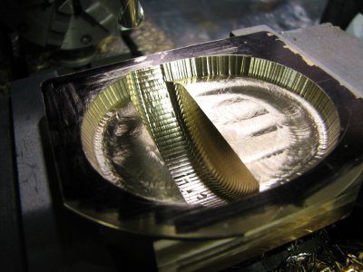
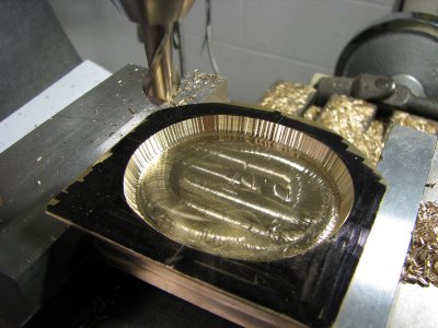
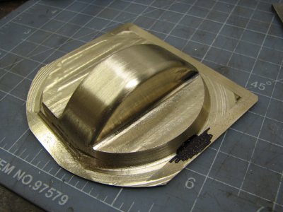
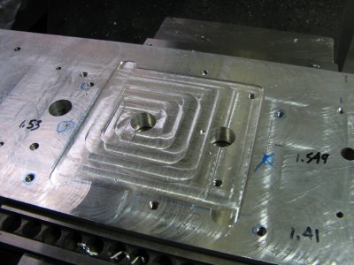
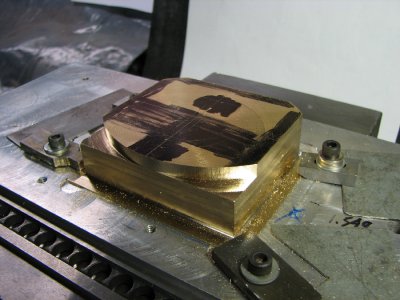
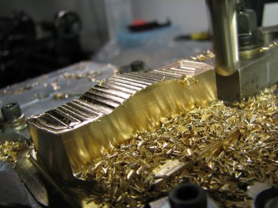
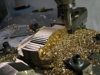
The next piece to make was the rear cover. As with the housing itself a die would have been nice but once again the amount of work to make a die set for a one-off would just take too much time. I started with a slice from a round brass bar as the shape is basically round. I then cut flats on the 4 sides to establish the overall width and height. The piece was then clamped in the vise on the mill and the inside shapes were cut. The step-out has a 26 degree angle so I made up a drill rod cutter to finish stepping it off. The reason for stepping the cuts to the layout line as opposed to just mounting it on the rotary table is because the shape follows the outer contours of the case and there are 6 separate radii to cut and try to blend. The outside was done on the rotary table because the radii overlapped and I didn't have to worry about a tangent point. With the recess cut I made up a radius step-off chart for the ring gear clearance and stepped it out. I will restate at this point that although the steps look large it doesn't take long to burr and stone them out. And they're not really that big, .005 at most.

IMG_8477.JPG IMG_8480.JPG IMG_8471.JPG
 
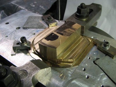
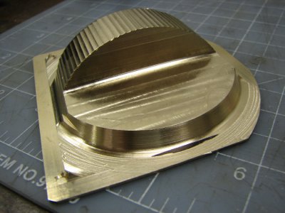
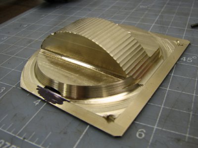
With the inside machining finished it was time to start on the outside. The piece was flipped over in the vise initially and the heavy material was removed. From there the vise was removed and the rotary table set up and indicated to center. With the flats on all four sides it allowed for some preliminary layout work, mainly radius center points. A fixture plate was made from a previously used aluminum fixture and the part was clamped down with some home-made mini clamps. As I had mentioned earlier when doing the inside there were 6 different radii to form the somewhat oval shape. The layout lines were wiggled and the cutting began. The shallow kick-out has a 26 degree angle on it so the special ground cutter was used to form this. After getting the radial work done. the part was squared up and the ring gear hump was stepped off to the proper radius. With the machining finished the hand work was started to smooth out the cutter marks and blend everything together. The flange was left square up until the end in case any further machining was required. At this point the extra material was removed with the bandsaw and the outer contour was filed and sanded to shape.
gbritnell

IMG_8513.JPG IMG_8484.JPG IMG_8486.JPG IMG_8492.JPG IMG_8498.JPG IMG_8505.JPG IMG_8507.JPG IMG_8510.JPG
 
Back
Top