- Joined
- Mar 22, 2013
- Messages
- 215
Gentlemen,
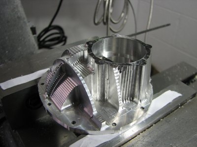
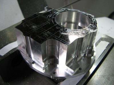
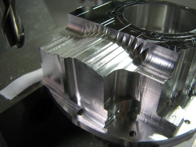
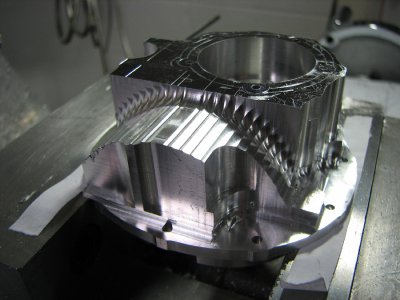
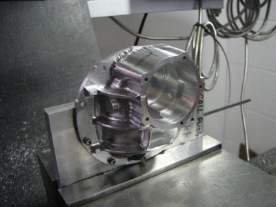
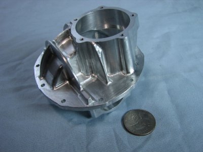
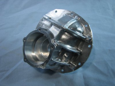
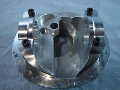
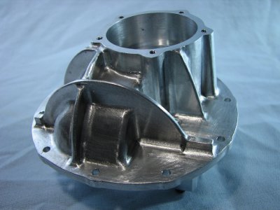
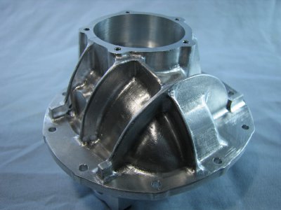
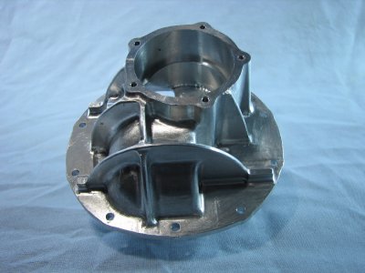
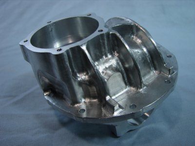
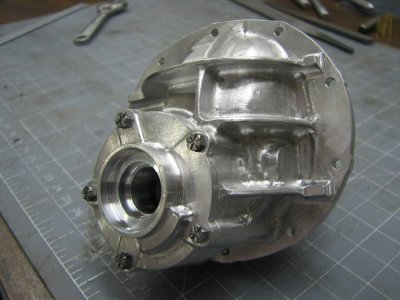
Over the years of attending model engineering show I was repeatedly asked "when are you going to make a car for your 302 engine?" At that point I really never gave it any thought. When I finished the T-5 transmission and would show it with the engine I got more of the same questions. This past year saw the building of the final piece of the driveline, the 9 inch Ford differential. It was at this point that the original question was given some serious consideration. Hopefully there will be enough time in the future to complete a full chassis, running gear, brakes, suspension etc.
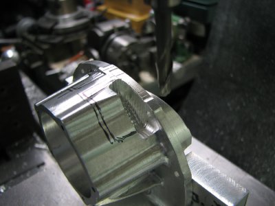
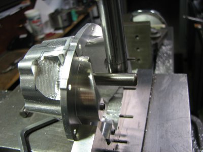
So with that introduction I will present to you the construction of the 9 inch Ford differential.
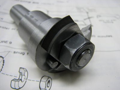
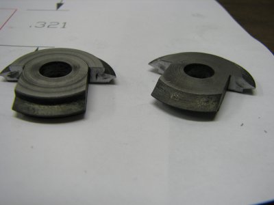
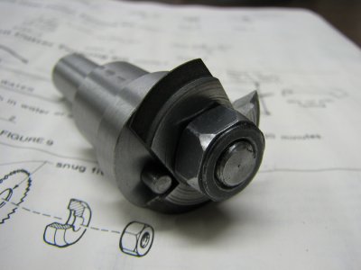
The first thing I had to determine was how I was going to make the ring and pinion gears. If I couldn't machine them then the project wouldn't go any farther. From my automotive background I knew that ring and pinion gears are in the class of hypoids, offset, curved tooth gears. But how to machine them. I turned to the internet and mainly Youtube to see how these gears are made. After lengthy investigation I realized that they were almost if not totally impossible to cut in the home shop. At this point an alternative type of gear but with similar characteristics was investigated. A series of build articles for constructing geared locomotives by a very talented engineer/machinist, Kozo Hiroako, for Live Steam magazine showed how to make skew bevel gears. A normal bevel gear set is where both pinion and ring gears have the same centerline but skew bevels have offset centerlines. Using all of the algebraic equations that the author had presented I tried to come up with pitches, tooth counts and offsets that would let me fit them into the dimensions taken from the full sized differential. The first stumbling block was my math knowledge (algebra) was a little rusty but with the help of some great people I got that issue resolved. I was even offered and given a spread sheet so that all I had to do was plug in numbers and the calculations would be generated. Whew! Once I got the numbers I needed the next step was to make some cutters and try out the equations. These were made from drill rod and hardened. I had never made this type of cutter before. The blanks were offset to give clearance to the cutting edge.
- - - Updated - - -
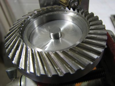
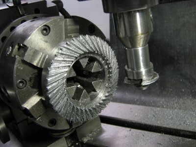
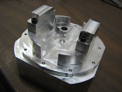
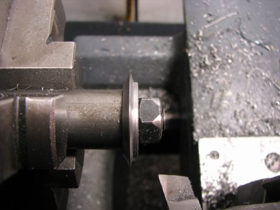
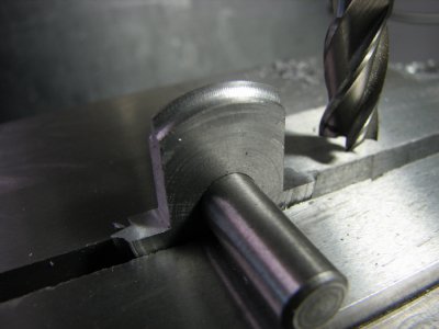
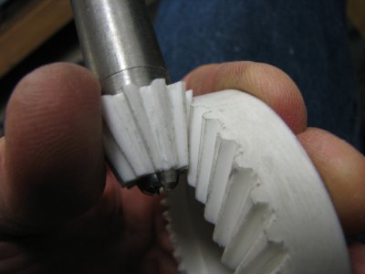
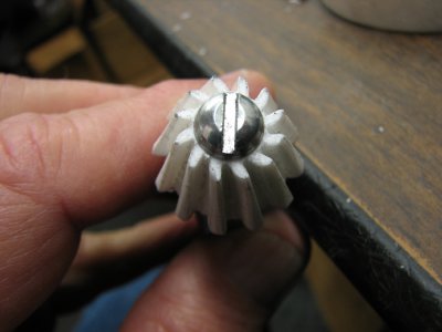
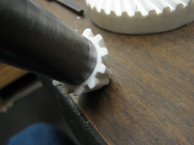
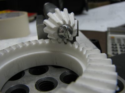
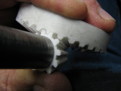
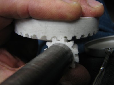
With the cutters and arbor finished the first task was to cut the gears from Corian to prove that everything would work. The dividing head was set up on the mill, the blanks were roughed out and mounted and the tooth cutting started. In the calculations for creating the tooth profile the cutter will only cut one side of the tooth form and then needs to be reversed to cut the other side. Along with this the blank needs to be offset from one position to another and the cutter centerline needs to be adjusted to create the correct profile and width.
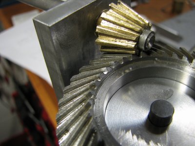
As you can see the plastic set came out quite nicely.


