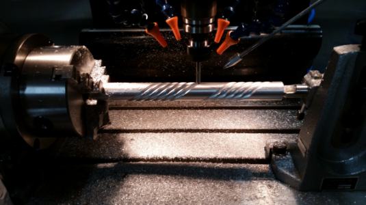
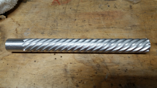
[How do I?] 4th Axis Setup

The R1.7 is the Z retract height,

It looks like it is trying to move the tool around the part, that's why the Y is moving.

I have no idea what the Y1.4722 Z-0.85 is about.

In the #2 picture, it looks like the part was rotated 180 around the X axis. Very strange. :cautious:

Also, the M9's, looks like it is turning the coolant off before drilling.:confused:

G28 G91 Z0. Go home and move Z to zero? This makes no sense unless there is a tool change.
 
The R1.7 is the Z retract height,

It looks like it is trying to move the tool around the part, that's why the Y is moving.

I have no idea what the Y1.4722 Z-0.85 is about.

In the #2 picture, it looks like the part was rotated 180 around the X axis. Very strange. :cautious:

Also, the M9's, looks like it is turning the coolant off before drilling.:confused:

G28 G91 Z0. Go home and move Z to zero? This makes no sense unless there is a tool change.


Thanks Jim,

I was answering my own question when you were posting. It was a post processor setting that was causing the problem.

Ah, I though R had something to do with radius. Need to brush up more on my g-code. :rolleyes:

In the second drilling op when I selected the hole as the tool orientation the CAM program flipped the X axis direction with no way I can find to change it. Once I fixed the post processor it didn't affect the program.

I had disabled the coolant to dry run the machine.

The G28 G91 Z0 is a default in the post processor I have. I usually manually edit those out. I need to find where in the post processor that is and change it.
 
I answered my own question. It was a post processor setting.

Another question. When setting the offsets in Mach3 for the Y and Z where the WCS is in the middle of the rotation axis is there a way to tell Mach3 what the part diameter is or do I just add edge find as normal and subtract for the radius?

I normally find the edge and subtract for the radius. You can look at it from the tool's point of view, looking down from the top. In that view, the part looks like a flat surface. The X,Y positions would be the same as machining a flat part, Z positions would be a function of the part radius. The CAM program should figure that out.
 
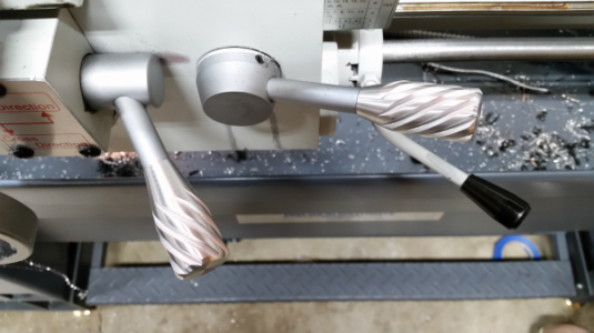
Cool!! What is it? Test piece?

Tom S.
 
Back
Top