[How do I?] 4th Axis Setup

The main issue is lack of documentation for us mere mortals. I guess that's how they sell "training" to further bloat the already outrages cost. :mad:

I can do the slots in a rotary mode, it just opens the top of the slot by 0.040" which is okay. I may do that if I cannot figure out the other or as Jim suggested, enter the radial moves manually into the g code.

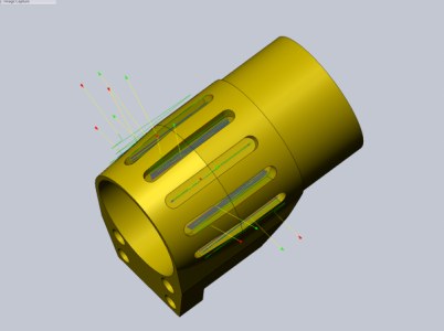
Here is the part with the radial tool paths for the slots and one with all the mill ops to do the part. A total of 7 milling ops with 2 setups. The main bore and front will be turned on the lathe first with the balance done on the mill.
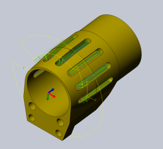
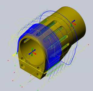
part2.png part3.png

I have some time before I need this part plus I need to finish the stepper motor mount for the rotary table and that will require a lathe which I won't have my new for another week.
 
Do the slots need to be parallel walled or are you wanting tapered slots?

And yes, that's the idea. No documentation so you need their training, but at least in many work environments there are co-workers you can collaborate with.
 
It was modeled as parallel but tapered is okay but I still want to figure out if the other is possible with what I have.
 
Got it!

In the 2D tool path setup under tool orientation if I select the face of the radius at the end of the slot it will create a tool path perpendicular to the slot. So for indexing I have to create a tool path for each slot.

Now to see if my post processor will work......

part4.png
 
I just gotta ask- What is the part? Nice work on the 3d work there! Impressive.
 
Ahhh..Ouuuuu.... Was this Aluminum or steel? Wait till I show my son that pic. I know he's dying to do something like that. :) really really cool!!!!
 
It is mostly aluminum. It is turning out to be an insane amount of work so I hope the results are worth the effort.
 
[SOLVED]
I have the 4th axis up and running. I modeled a test part to verify it is working as it should but the CAM posts is odd.

I was able to modify the Mach3 post processor to enable the 4th axis. I made a simple test part of three holes drilled around a cylinder so these are just indexing moves. I was able to create a post but I don't understand why it wrote the code the way it did. In Solidworks the WCS is at the center of the cylinder with the rotational axis being X. In HSM Works the tool orientation for each hole is set by selecting the hole. The first drilling op seems to work fine but the other two holes have Y & Z moves it shouldn't.

This is just a test model. I'm not actually making a part, just cutting air to verify is is working properly.

The cylinder is 1.5" dia. x 3" long, the hole is 0.25" deep.

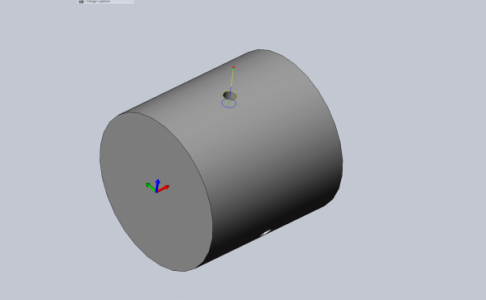
Screen shots of the tool paths.

Hole #1
Test01.png


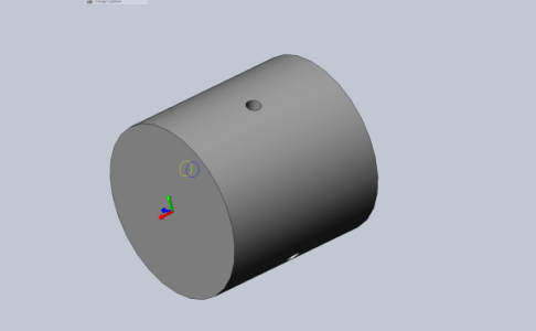
Hole #2, note the x axis direction changed?
Test02.png


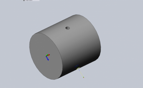
Hole #3
Test03.png

I have added comments in (blue)

G-Code:
(THREE HOLES ON CYLINDER)
(T68 D=0.248 CR=0. TAPER=118DEG - DRILL)
G90 G94 G91.1 G40 G49 G17
G20

G90

(DRILL1)
M5
M9
T68 M6
(6.3MM DRILL)
S2775 M3
G54
G0 A0.
M9
G0 X1.5 Y0.
G43 Z2.1 H68
Z1.7
G98 G81 X1.5 Y0. Z1.25 R1.7 F8.5 (all looks good so far except what is the R1.7 for?)
G80
Z2.1
G0 Z2
G90

(DRILL2)
A240.
M9
G0 X1.5 Y1.8187 (Y should stay at Y0?)
G43 Z-1.05 H68 (a negative Z move?)
Y1.4722 Z-0.85 (???)
G81 X1.5 Y1.0825 Z-0.625 R1.7 F8.5 (Y??, Z??, R??)
G80
Y1.8187 Z-1.05 (Y??, Z??)
G28 G91 Z0. (Z should be Z2.1)
G90

(DRILL3) (Similar to DRILL2)
A120.
M9
G0 X1.5 Y-1.8187
G43 Z-1.05 H68
Y-1.4722 Z-0.85
G81 X1.5 Y-1.0825 Z-0.625 R1.7 F8.5
G80
Y-1.8187 Z-1.05

M9
G0 Z2
A0.
G28 X0. Y0.
M30

It seems like the Y & Z are trying to follow the Model WCS vs the tool orientation?
 
Last edited:
I answered my own question. It was a post processor setting.

Another question. When setting the offsets in Mach3 for the Y and Z where the WCS is in the middle of the rotation axis is there a way to tell Mach3 what the part diameter is or do I just add edge find as normal and subtract for the radius?
 
Back
Top