POTD was finishing off a project for my wife of 28 years as of tomorrow. We had our house built in 1993 and have been slowly updating things room by room. Latest project was adding motion sensor LED lighting on the stairs going down to the lower level of the house. She picked these up off Amazon; pieced together a package with a couple of sensors, hooded LED lights and a transformer. I didn't take pictures of the LED installation, but it was pretty simple: Hole saw through the drywall, and pop them into place. They have spring clips on the sides for retention. They're wired in parallel to the motion sensors which in turn are powered by the transformer.
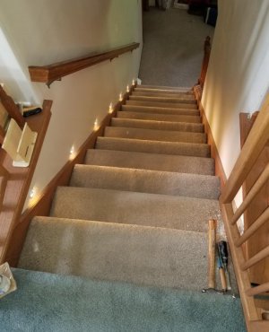
A look down the stairs with the LED's lighting the way
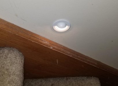
One of the hooded LED bulbs.
POTD involved dressing out the motion sensors at the top and bottom of the stairs. She bought a couple of blank switch plate covers and I took over from there. First the top of the stairs . . .
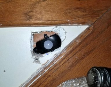
I chiseled out the drywall to clear the sensor so it'd set sub-flush to the wall. Plan was to mount the sensor to the cover plate and screw the cover plate to the wall. The sensors have adjustments for sensitivity and on time on the back side, it was easier to set them by attaching them directly to the plate to get to the back side of the sensor.
Chiseled out the drywall to get the sensor sub-flush of the wall.
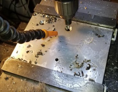
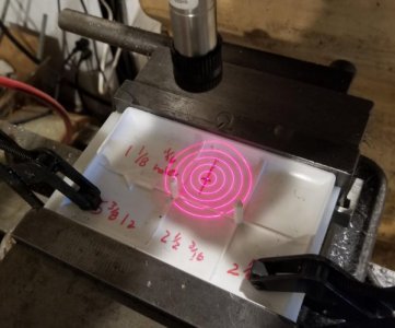
Took a few measurements for the center of the sensor to fit through the plate and laid out the dims on the back of the plate. The sensor dome is 0.910" diameter, many ways to make that hole and figured a drill bit would be one that would not work. So, set up the plate on my Bridgeport and ran a CNC routine to make a 1/2" end mill cut a 0.910" hole. Really like the CNC for this type of thing, don't know if I'll ever use my boring head again. It's soo simple to enter V18 hole diameter (0.910"), V49 cutter diameter (0.500") and issue a G76 command and watch the mill do its thing.
Found the center of the 0.910" hole with a laser center finder
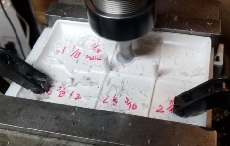
Quick CNC routine to cut the 0.910" clearance hole for the sensor dome. Milled away some of the back-side ribbing to allow the sensor to set flat on the back of the plate.
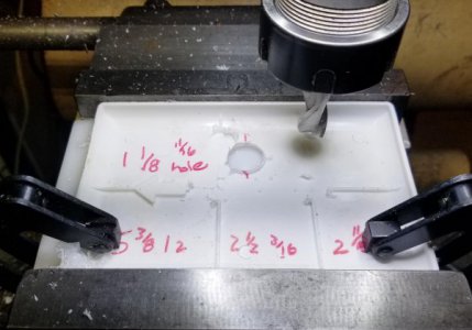
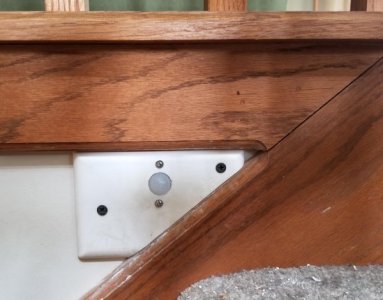
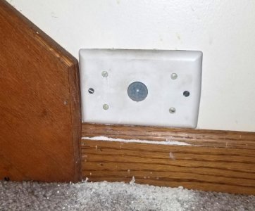
Then band sawed and sanded the plate to fit into the angled area of the trim on the stairs. Screwed the sensor to the plate, then screwed the plate to the wall.
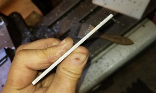
Cut the plate to size and sanded the edge.
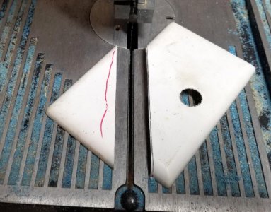
Plate and sensor in place. Will paint the screw heads with a paint marker.
My wife bought a different sensor for use at the bottom of the stairs. Don't know for sure, but guessing she picked this one up because it was cheaper than the one at the top of the stairs. Lot bigger footprint on this one. Mounting scheme was the same: Knock in a clearance hole for the sensor dome, mount the sensor to the plate and screw the plate to the wall.
Sensor at the bottom of the stairs.
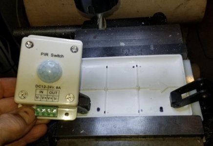
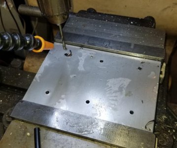
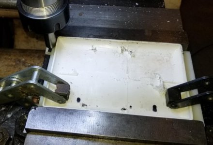
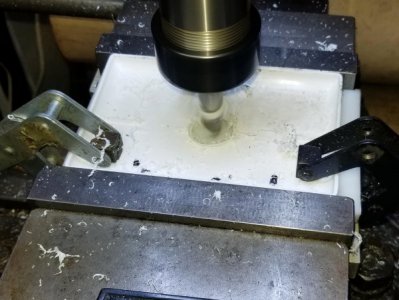
Started on the BP by milling away some of the plate's back-side ribbing so the sensor could set flat on the plate. Then used an edge finder to locate the plate and moved the spindle to the center of the plate. Then ran the same CNC routine to knock in a 0.910" clearance hole for the sensor dome.
Milling away some of the plate's back-side ribbing
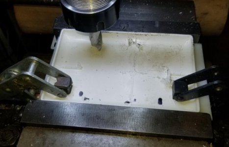
Edge-finder to locate the plate
CNC routine to knock in a 0.910" clearance hole
Sensor set in place
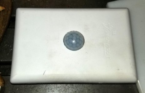
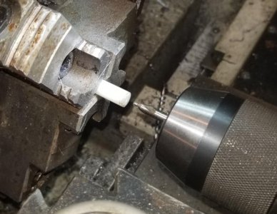
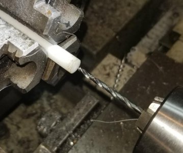
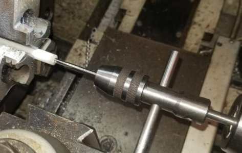
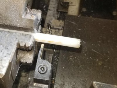
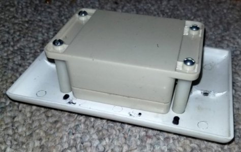
This sensor was quite a bit larger than the one at the top of the stairs. I ended up making Delrin bosses about 1.25" long to fill the gap between the sensor's mounting flanges and the mounting plate. The bosses were tapped with 6-32 threads on both ends.
Center drill, tap drill, tap and parted the bosses. Flipped them over to face and drill/tap the back sides.
Lower sensor screwed to the bosses which in turn are screwed to the mounting plate
Hooked the wiring back up to the sensor and screwed it to the wall. Works great, nice to have passive lighting on the stairs, especially if your hands are full and you're trying to bump the light switch on.
Final mount, will paint the screw heads with a paint marker.
Thanks for looking.
Bruce


