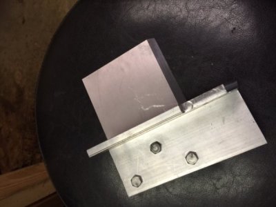
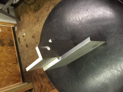
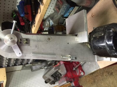
2 X 48 Belt Grinder (again)

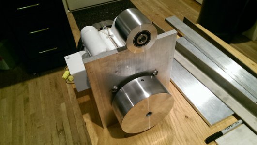
Thanks Dave. I had not considered that. I have finished the pulley but not run it yet to see how much vibration I get. If I have an issue I will move forward with your suggestion and rework the surface.
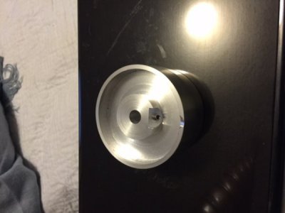
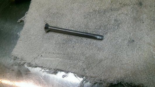
I was able to cut most of the threads with a standard tap. I had about 3 unfinished threads at the bottom of the hole so I made a poor mans tap out of a SS bolt. That easily cut the last few threads and the set screw goes in smoothly.

Tap:
26478093430_dd8883cc22_h.jpg

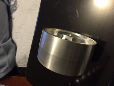
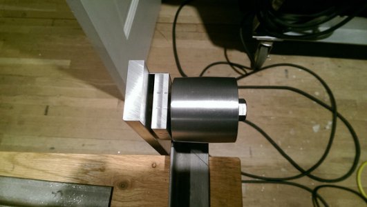
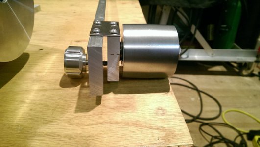
Finished pulleys (unless Dave is correct)
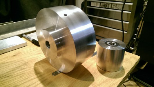
26683906171_77c426c76d_h.jpg 26683907061_d2760c1b0a_h.jpg

Robert
 

Attachments

  • 26478093430_dd8883cc22_h.jpg
    26478093430_dd8883cc22_h.jpg
    64.8 KB · Views: 156
  • 26683906171_77c426c76d_h.jpg
    26683906171_77c426c76d_h.jpg
    69.8 KB · Views: 156
  • 26683907061_d2760c1b0a_h.jpg
    26683907061_d2760c1b0a_h.jpg
    66.5 KB · Views: 155
  • 26478093430_dd8883cc22_h.jpg
    26478093430_dd8883cc22_h.jpg
    64.8 KB · Views: 155
  • 26683907061_d2760c1b0a_h.jpg
    26683907061_d2760c1b0a_h.jpg
    66.5 KB · Views: 153
  • 26683906171_77c426c76d_h.jpg
    26683906171_77c426c76d_h.jpg
    69.8 KB · Views: 154
  • 26478093430_dd8883cc22_h.jpg
    26478093430_dd8883cc22_h.jpg
    64.8 KB · Views: 150
  • 26683906171_77c426c76d_h.jpg
    26683906171_77c426c76d_h.jpg
    69.8 KB · Views: 151
  • 26683907061_d2760c1b0a_h.jpg
    26683907061_d2760c1b0a_h.jpg
    66.5 KB · Views: 151
  • 26478093430_dd8883cc22_h.jpg
    26478093430_dd8883cc22_h.jpg
    64.8 KB · Views: 150
  • 26683906171_77c426c76d_h.jpg
    26683906171_77c426c76d_h.jpg
    69.8 KB · Views: 151
  • 26683907061_d2760c1b0a_h.jpg
    26683907061_d2760c1b0a_h.jpg
    66.5 KB · Views: 150
  • 26478093430_dd8883cc22_h.jpg
    26478093430_dd8883cc22_h.jpg
    64.8 KB · Views: 149
  • 26683906171_77c426c76d_h.jpg
    26683906171_77c426c76d_h.jpg
    69.8 KB · Views: 151
  • 26683907061_d2760c1b0a_h.jpg
    26683907061_d2760c1b0a_h.jpg
    66.5 KB · Views: 150
Last edited:
Maybe drill the hole to size for threading to the bore, then thread the top inch or so. Make a pin that fits inside the hole and use it as an extension to the set screw.

Greg

Oops, too late
 
You cannot make this pulley in one operation on the lathe then set screw it and then mount it on the motors shaft and expect it to run true. The chances of it running true with this process are slim to none. If you want it to run true, you must finish the bore, leave the OD roughed out and put in the set-screw(s). Then return to the lathe with a turned shaft the diameter of the motors shaft in the chuck. Mount the unfinished pulley, probably using a ball bearing/dead center in the tail stock. And then finish the pulley. Hope this helps…Dave.
I don't know why not. I made my direct drive pulley in one shot on the lathe, Bored it, cut the OD, took it off , drilled the set screw hole and it runs as true as it could possibly be.
Finished Drive Wheel 2.JPG Finished drive wheel.JPG
 
Last edited by a moderator:
That is a very elegant pulley Mark. I thought about removing some of the center material like you did to reduce the mass. Not sure it is necessary though.
I test ran my pulley last night. It runs very smoothly with almost no vibration. Better to be lucky than good!
3450 RPM and you can't tell it's moving in the video!

That is a very elegant pulley Mark. I thought about removing some of the center material like you did to reduce the mass. Not sure it is necessary though.
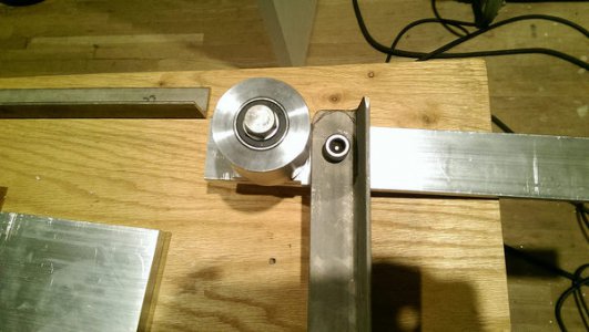
I made some progress on the tracking pulley design.
26657476272_7715d6bc35_h.jpg
26657474672_e1a21f1556_h.jpg

Is anyone but me worried about my tracking pulley turning at 8000 PRM?! Will the bearings hold up?
Is there any reason I would want tracking adjustment moving the pulley left and right (rotation in x,y plane) rather than tilting it up down (rotation in x,z plane.)?

R
 

Attachments

  • 26657476272_7715d6bc35_h.jpg
    26657476272_7715d6bc35_h.jpg
    46.2 KB · Views: 148
  • 26657474672_e1a21f1556_h.jpg
    26657474672_e1a21f1556_h.jpg
    50.7 KB · Views: 148
  • 26657476272_7715d6bc35_h.jpg
    26657476272_7715d6bc35_h.jpg
    46.2 KB · Views: 148
  • 26657474672_e1a21f1556_h.jpg
    26657474672_e1a21f1556_h.jpg
    50.7 KB · Views: 147
  • 26657476272_7715d6bc35_h.jpg
    26657476272_7715d6bc35_h.jpg
    46.2 KB · Views: 148
  • 26657474672_e1a21f1556_h.jpg
    26657474672_e1a21f1556_h.jpg
    50.7 KB · Views: 147
  • 26657476272_7715d6bc35_h.jpg
    26657476272_7715d6bc35_h.jpg
    46.2 KB · Views: 146
  • 26657474672_e1a21f1556_h.jpg
    26657474672_e1a21f1556_h.jpg
    50.7 KB · Views: 147
  • 26657476272_7715d6bc35_h.jpg
    26657476272_7715d6bc35_h.jpg
    46.2 KB · Views: 147
  • 26657474672_e1a21f1556_h.jpg
    26657474672_e1a21f1556_h.jpg
    50.7 KB · Views: 146
Last edited:
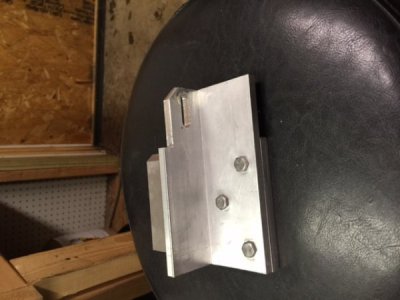
Note the thin strip of metal connecting the pulley carrier to the upper arm. That is the "hinge." There will be a knurled thumb screw extending through the arm and contacting the base of the pulley carrier. That will deflect the pulley upwards. I am thinking about a single screw although I could do one screw in the front and one in the rear which might allow some adjustment in the other plane? Thoughts?
R
Oh...... I see it now. One screw should suffice. The framework should keep everything parallel . you shouldn't have to worry about the other plane as long as the frame is sturdy and does not flex anywhere. That was an issue I had to address and it took a little reenforcement of the frame to correct it. You may have been better off to use some square tubing instead of the angle iron, then again, the angle may work just fine.
 
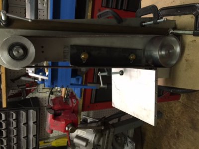
For Mark!

26683917441_5bc41c7070_h.jpg

I have sanding belts on order from MMC. Hopefully Tuesday on those.
I guess I need to start working out the table/rest. I have a nice piece of SS for that. I need it to tilt up to 45 deg and be able to move in and out from the belt appropriately.
R
 

Attachments

  • 26683917441_5bc41c7070_h.jpg
    26683917441_5bc41c7070_h.jpg
    46.2 KB · Views: 148
  • 26683917441_5bc41c7070_h.jpg
    26683917441_5bc41c7070_h.jpg
    46.2 KB · Views: 148
  • 26683917441_5bc41c7070_h.jpg
    26683917441_5bc41c7070_h.jpg
    46.2 KB · Views: 147
  • 26683917441_5bc41c7070_h.jpg
    26683917441_5bc41c7070_h.jpg
    46.2 KB · Views: 148
  • 26683917441_5bc41c7070_h.jpg
    26683917441_5bc41c7070_h.jpg
    46.2 KB · Views: 150
Last edited:
looking good, It almost looks like the angle iron sticks up just a bit to high or should it be on the other side so that it is not in the way of the belt, What are you using to tension the belt. I'm keeping an eye on this build for when I build one.
 
I'm posting some photos of my table. it may give you some ideas. it tilts to 45 and moves in and out to adjust the gap. mounts and adjusts with one bolt.


table 2.JPG table mock up (2).JPG table.JPG table3.JPG tension device.JPG
 
Back
Top