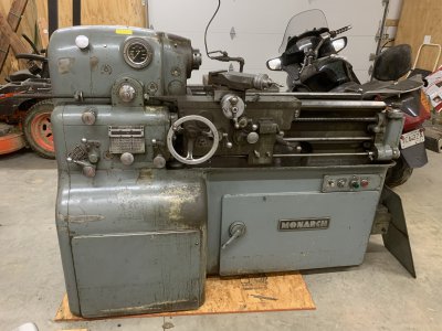
1964 10EE lathe

I did quite a bit of reading om practical machinist on fixing the DC mechanism in these. Two possible routes became obvious, basically replacing the DC controller, or replacing the DC motor with an induction (standard AC) motor and vfd.

The monarch 10EE is a bit unusual for a lathe in that the spindle is ungeared. It is a straight through shaft and however fast the belt drive turns that end is how fast the chuck or whatever is mounted on the working end will turn. And yet you get this incredible range of useable speed, like 10 rpm to 4000 rpm on mine. This is done via a DC motor which has torque over a fairly broad range of rpm, plus a reduction gear mounted on the motor, giving direct motor rpm out, or IIRC a 5:1 reduction.

The challenge with the induction motor plus vfd route is even with a good vfd, 10-4000 rpm on the spindle is a 400:1 range of rpm to operate. Many vfd machines we see today run 20-2000 rpm, 100:1, by using two or three geared speed ranges. Also, a vfd driven motor roughly creates the same torque at speeds less than the design speed of the motor. HP = rpm * torque * constant, where constant is a number which depends on units used. So if torque is constant, than as rpm drops, so does HP. On a lathe if you are looking for a certain SFPM cutting speed, you go slower on bigger (larger diameter) parts. Larger diameter means less leverage for the motor, so the motor needs more torque to give the same force at the cutting tool at that SFPM. So a VFD isn’t to optimum configuration for getting power to a machining tool as we reduce rpm below the motors rated speed. On the other end, as we increase rpm above the motor’s rated speed, vfd’s have to reduce the torque as speed increases (above the 60Hz speed of the motor), to keep the motor from exceeding its rated HP output. This matches well with what we want for most machining. Turning faster is associated with smaller endmills or smaller diameter workpieces in the lathe.

One takeaway from this is if you have a vfd machine with multiple speed ranges and you need the most cutting power, you should opt for the lowest speed range that will give you the desired cutting speed. So if your lathe has ranges 50-500 and 200 to 2000, and 400 rpm is your desired cutting speed, you are better off using the 50-500 rpm range. The high range will of course still give you the option of 400 rpm, but less cutting power. Just like you can use third gear at 20mph in your manual transmission car, but if you want to accelerat, downshift to 2nd or first.

Ok, rhe point of all that explanation is that a VFD driven motor isn’t going to give you good cutting performance over a spindle rpm range of 10-4000 rpm. There are two ways to help this along. One is to use some gearing. The other is to use an oversize motor.

The 10EE does have that reduction gear in its design. The challenge is that the reduction gear is part of the DC motor assembly, between the DC motor and the drive pulley. So you can’t just take the pulley off and put it onto a VFD driven motor without losing the reduction gear. Quite a few 10EEs out there have been converted in just that way, the reduction gear is discarded along with the old motor. Even with a ridiculously oversized motor (commonly up to 10HP) the low rpm performance suffers. Singke point threading is one area that this can become an issue. Since that is one area where the classic 10EE shines, it is a shame to sacrifice capabilities in that area.

A very good solution to this is to re-use the original reduction gear unit. This is somewhat complicated to do in that the original DC motor is not a simple keyed shaft but rather a splined shaft into the reduction gear. This has been solved many ways, such as making a keyed shaft to spline adapter, or more commonly just cutting off the spline end of the original DC motor and putting a keyway on the cut end, along with a coupling.

So, a large (5-10HP) AC induction motor, reduction gear adapter and VFD is probably the cleanest solution. That’s not necessarily cheap, unless you can find a bargain on a good used AC motor and suitable VFD.

The option I took was to preserve the whole motor assembly and build a new DC motor control system. In retrospect that certainly wasn’t the quickest solution to a functional lathe, and is only practical in that I do have a background that includes electronics. I also wanted to run the whole thing off single phase rather than a phase converter.

One thing to think about is modern high end VFDs will offer Field Oriented Control (FOC). When you use this control mode with an encoder on the motor, you can see 1000:1 torque range.

Here is an excerpt from an Allen Bradley whitepaper (publication DRIVES-WP002A-EN-P).


1614630213262.png

Note that Field Oriented Control (FOC) is branded by AB as "Force Technology". Without an encoder, you get about a 20% gain on a sensorless vector controlled (SVC) VFD. Adding the encoder gets you to the 1000:1 constant torque speed range, in line with a DC drive, as well as much better speed regulation. They also offer better torque bandwidth and regulation than a comparable DC drive.
 
Very good summary. I do think there is one more important point on the 3 phase motor. Get one with 4 (1800 base RPM) or 6 (1200 base RPM) poles, NOT a 2 pole (3600 base RPM). For a given slow speed the 4 pole has twice the torque, the 6 pole has three times the torque of a 2pole motor; and it won't hurt them at all to spin up to 3600 or even a bit more RPM.

I will be using a 6 pole C frame 7.5 Hp 3 phase motor on my 10EE that i plan to rebuild late this spring. The VFD will be set to spin the motor and spindle from 60 to 4000 RPM . Back gear gives another 6:1 reduction. i already have another 10EE that was rebuilt this way.
Karl,
Another way to look at that is torque at 60Hz. Since HP = torque * RPM * (conversion constant):
A 2 pole motor produce 1 HP spins twice as fast as a 4 pole 1 HP motor. The two pole motor has 1/2 the torque.
But you can put a 2:1 pulley on the 2 pole motor and get the same RPM and torque as the 4 pole motor. Ignoring pulley loss you haven't really gained anything. It's really just a matter of matching the RPM of the motor you're replacing to avoid having to add that extra 2:1 pulley.

A 6 pole motor is a close match to the original Monarch torque curve. And by going from the typical 3 HP to 7.5 HP you've thrown in a good bit of extra torque to make up for the fact that AC motors don't usually deliver good torque at really low RPM. With the back gear you are set. I think I already alluded to the fact that If I were starting over I would go this route.
 
Last edited:
One thing to think about is modern high end VFDs will offer Field Oriented Control (FOC). When you use this control mode with an encoder on the motor, you can see 1000:1 torque range.

Here is an excerpt from an Allen Bradley whitepaper (publication DRIVES-WP002A-EN-P).


View attachment 357631

Note that Field Oriented Control (FOC) is branded by AB as "Force Technology". Without an encoder, you get about a 20% gain on a sensorless vector controlled (SVC) VFD. Adding the encoder gets you to the 1000:1 constant torque speed range, in line with a DC drive, as well as much better speed regulation. They also offer better torque bandwidth and regulation than a comparable DC drive.

Yep, VFD's are getting more and more advanced. I wouldn't get too wrapped up in claims by a company about the performance of their product, this white paper certainly has a bit of marketing spin. Ironically the Parker 514 has an encoder option that adds stability and speed range too, so this is not a completely new concept. Any engineer will tell you that feedback improves stability. All of these technologies are basically trying to estimate the actual speed (or slip) of the motor. Going to a direct measure instead of an estimate gives a more accurate measurement to work from. Either way, via the Parker or Allen Bradley approach, adding an encoder is an additional complexity. The more modern hall-effect encoders make this much easier than it was in an earlier era.

Modern production CNC equipment designers will probably want to take a close look at this type of technology ("Force Technology"). What is the sweet spot for home/hobbiest machinists, or even job-shop machinists that want a good manual lathe? I'd guess right now the oversized motor and vector control VFD w/o any other technology is probably the best on the basis of cost, and easiest to maintain for the home shop, less confusing if you attempt resale. In another 10 years I'm sure that will change.
 
Last edited:
Beautiful !!! You do NICE work.

Please show what you used to lift the lathe onto the work platform.
I have a small gantry crane that I made many years ago, using a 2" x 3" x 3/16" A36 rectangular tube frame. It bolts together. Unfortunately I don't have any pictures of it and it is currently disassembled. Honestly it is not suitable for lifting that much weight with a safe "overhead" lifting margin, even though I'd stripped quite a bit of the weight off.
 
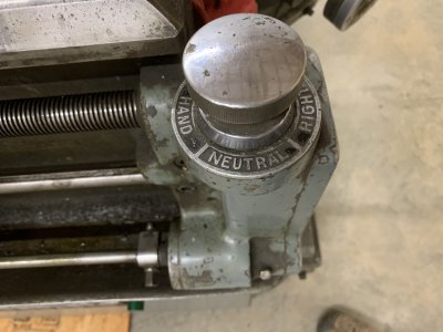
So I made the very questionable decision to keep the DC motor and install a new controller based around the Parker modules. From there I decided to jump off the deep end and build a microcontroller-based circuit to keep everything straight and give a simple one dial speed control. This particular machine has what Monarch called a "Electrical Lead Screw Reverse" (ELSR). Or may they used "Electronic"? That sounds pretty fancy but it is really just an "off switch" driven by adjustable stops. A fancy mechanical adjustable limit switch. The tailstock end of the lathe has a dial that selects between forward, neutral, or reverse for the motor and therefore the spindle.
IMG_3098.JPG

Monarch also offered some 10EE variants/options that allowed you to set a different speed for forward and reverse. This can be helpful for cutting threads, where you may want to move quickly while out of the cut, and then run a cutting pass more slowly. I figured WTH, I'll add this to my design.

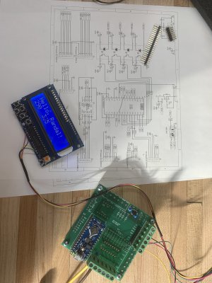
So I'm going to throw low voltage digital control circuits in with lots of high AC and DC voltage, including inductive (motor) loads and high frequency switching in the Parker controllers. That has the ingredients for serious RF interference problems so I figured I'd better design my digital circuitry with care. Digital circuits are generally not tolerant of signals that are even briefly greater voltage than the 5V or 3.3V power supply, or less voltage than ground (any negative voltage). Not tolerant, in this case doesn't just mean a bad logic value, it means the digital circuit dies. So while the basic logic needed is pretty simple, keeping things robust is more complicated. Only time and use will tell if I'm doing this right.

I picked the Arduino family of microcontroller development environment. My background is offended by that world of trying to gloss over the all the details and reduce programming to what they call "sketches". I've worked professionally with Motorola 68701, 68HC11, Microchip 16C and 17C series, Texas Instruments MSP430 microcontrollers, as well as a fair amount of embedded linux 32-bit systems. But the advantages of the Arduino environment are free development software based on C/C++, USB port interface to a programming computer, and low cost microcontrollers that are available in packages conducive to through-hole circuitry. Actual microcontroller chips tend to come in surface mount packages with .025" lead spacing, or other bizarre package/mounting options. While I've seen a few projects where people have done that with a home soldering iron, my eyes and soldering skills would be hard pressed to do that reliably. The Atmel 8-bit microcontrollers are pretty decent capability, have a good C-compiler port, and at $10 or less for a microcontroller break-out board for the 20MHz Nano every, are a good value for this project.

IMG_3431.JPG

I design up a circuit with a lot of protection for the interference issues discussed above. Optical isolation buffers (opto-isolators) to keep the high voltage noise/transients from damaging the circuits. RC low pass filters to reduce noise, as well as debounce switches (I hate software debouncing, offends my sense of good design). Zener diodes as transient protection.

The main control into the Parker 514 is an analog voltage input between +10 and -10volts. The 514 provides a +10V and -10V output, so a potentiometer (variable resistor) can be easily set up. Of course, forward is selected by 0 to +10volts and reverse by 0 to -10v. I really don't like the idea of a speed dial on the lathe also selecting forward vs reverse. (Ever run a carbide insert backwards? Be prepared to change out the insert.) I won't go into more details on the 514 and 506/7 interface, it gets a bit messy. I also wanted an interlock circuit. Monarch's original design had lots of good safety features, like the ELSR needs to be in neutral to power on the lathe, and won't spin up if the spindle lock is set.

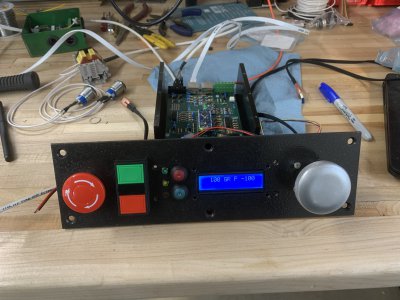
I wanted the digital part of my circuit to fit in the original on/off switch panel, an area roughly 2.75" x 11". (See the previous post with the protruding on button and recessed off button for a picture of that original switch panel). So I designed up replacement panel accordingly.

IMG_3584.JPG

The e-stop and square red-green buttons go directly the main power contactor. The large knob on the right goes through a bushing to a digital encoder (or rotary pulse generator). I didn't want a delicate little knob for speed control, so this is more in size with other working controls on the machine. The center LCD screen displays my two speed set-points, 100rpm forward and -100rpm backwards. The letters reflect "S"top/"G"o, "F"orward/"R"everse. The P is a diagnostic for the lathe "state", in this case "P" stands for power-up. This is still on the bench test stage obviously.
 
Yep, VFD's are getting more and more advanced. I wouldn't get too wrapped up in claims by a company about the performance of their product, this white paper certainly has a bit of marketing spin. Ironically the Parker 514 has an encoder option that adds stability and speed range too, so this is not a completely new concept. Any engineer will tell you that feedback improves stability. All of these technologies are basically trying to estimate the actual speed (or slip) of the motor. Going to a direct measure instead of an estimate gives a more accurate measurement to work from. Either way, via the Parker or Allen Bradley approach, adding an encoder is an additional complexity. The more modern hall-effect encoders make this much easier than it was in an earlier era.

Modern production CNC equipment designers will probably want to take a close look at this type of technology ("Force Technology"). What is the sweet spot for home/hobbiest machinists, or even job-shop machinists that want a good manual lathe? I'd guess right now the oversized motor and vector control VFD w/o any other technology is probably the best on the basis of cost, and easiest to maintain for the home shop, less confusing if you attempt resale. In another 10 years I'm sure that will change.

For sure, whitepapers are marketing tools for us nerds :) But I do not believe the specifications to be inflated. DC drives hold a very special place in the portfolio of motor control as they have been able to do things that AC drives are just starting to match (and AC drives can do things DC drives can't touch).

The encoder is included for applications where the highest speed range is required, or more commonly, the smoothest and most accurate application of torque is required.

These drives are not specifically designed with machine tools in mind. More or less, our technological needs are very basic. The motor drive is put to the test when super precise control of the load is needed. One example is using a roll to set the tension in a continuously moving web of product (packaging, printing, etc.). Any variation in applied torque will be visible in the end product.

Technology trickle down is a great thing. Someone with a crazy application must have the absolute best motor control, 20 years ago, and now the controls we have access to today includes that same technology as a standard option. Pretty cool.
 
Here's a better picture of the 10EE when I got it. It did come with a tailstock, of which the quill lock handle is barely visible sitting in the back right corner of the chip pan.
IMG_3117.JPG
 
Looking great, rabler. I have to admit I tend to glaze over when discussions turn to microvolts and optoisolators but you’ve got a way of writing that keeps even us fools engaged. Thanks for that! :encourage:

-frank
 
Man, rabler, your analysis and design direction is excellent. Possibly like you, this project would be a cross section of my professional career, and something that would be exciting to take on, and I applaud you for it.

Please continue showing us your progress. I suspect for 10EEs, the price is about to go up and the availability about to go down, with all the drooling going on out here in cyberspace.
 
Back
Top