
Ok guys my wiring knowledge is residential 110 220, aoutomotive in the old days. My question is what’s necessary on sb 10l 3 phase. There is an old disconnect slo blow, fuses push button reversing switch, maybe a transformer, and a distribution box of some sort. What can I scrap, remove. Any help would be appreciated, and yes I have 3 phase. Thanks

-
Welcome back Guest! Did you know you can mentor other members here at H-M? If not, please check out our Relaunch of Hobby Machinist Mentoring Program!
You are using an out of date browser. It may not display this or other websites correctly.
You should upgrade or use an alternative browser.
You should upgrade or use an alternative browser.
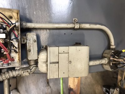
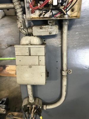
What’s the boxes southbend
- Thread starter Jeffro
- Start date
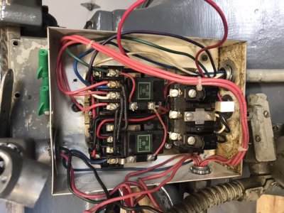
Yes it is after a couple of hours searching on the web and crawling through the wiring. The lathe also has a push button reverse forward off. All Allen Bradley.
I read that the starter is necessary to not fry the motor. I also picked up a 13” same place. The starter on the 13” is far less complex. Do I need the disconnect and starter. I don’t know what the other item is. Appears to have a heat sink.
I read that the starter is necessary to not fry the motor. I also picked up a 13” same place. The starter on the 13” is far less complex. Do I need the disconnect and starter. I don’t know what the other item is. Appears to have a heat sink.
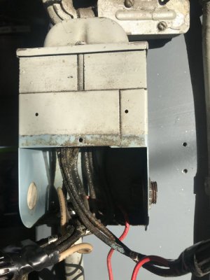
I agree with the old if it ain’t broke don’t fix it. However, it’s broke. I direct wired motor ran fine. I previously wired through to motor starter. I got nothing. This lathe was disassembled and mostly refurbed. The disconnect was and is bolted to the legs. I removed the electrics as a unit. While attempting to troubleshoot last night. The red leg, goes to the stop button Is it connected in the motor starter. Visual inspection didn’t reveal connection. The lathe ran when purchased. I don’t know if it reversed.
- Joined
- Feb 25, 2021
- Messages
- 3,130
That is a transformer. Often a transformer is used to create a lower voltage, which is run through the For/Rev/Off switch and then the contactor(s), so that the voltages at the switches are lower. Somewhat safer and makes the switches last a bit longer. If it is not working then the motor starter probably won't work.
It should not be "between" the motor starter and motor(?). Generally it is in parallel (T'd off) with 2 of the 3 incoming power wires to the starter for the high voltage side, and the low voltage side will be connected to the switches and/or starter magnetic coil.
It should not be "between" the motor starter and motor(?). Generally it is in parallel (T'd off) with 2 of the 3 incoming power wires to the starter for the high voltage side, and the low voltage side will be connected to the switches and/or starter magnetic coil.
Last edited:
- Joined
- Feb 13, 2017
- Messages
- 2,138
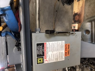
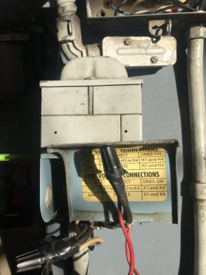
Without getting down and dirty with the connections, and assuming the transformer is indeed electrically between the starter and motor, my first guess would be a "poly phase buck-boost" transformer. The label on the incoming line indicates a 208 volt supply. A retrofit motor would likely be rated 240 volts. (or 240/480 nine wire, wired for low voltage)Anybody know this is, it’s function, and necessity. It is between motor starte and motor.
A 240 motor will run on 208, but. . . It runs warm and does not produce full shaft HP. Older motors are often rated 208/220. Newer motors are rated 220/240, having less "iron", hence a weaker magnetic signature. From the looks of the installation, the machine came out of an industrial application. This would imply the necessity for full power at times. There are several other reasons for adding a buck-boost setup for the motor, I am just speculating the more likely.
The size of the wires versus the size of the transformer points to a low voltage (and high current) throughput. Buck-boost transformers are very common, and relatively low cost. They are designed to add (or subtract) a given voltage to the line. 12/24 and 16/32 are the most common I have ever worked with. They are wired as an "auto-transformer" to, in common use, bring 208 volts up to 220 volts. (12 volts) They are also used to provide low voltage for controls and other uses. But in this install, most likely as a buck-boost. Simply put, if there are 3 wires in and three wires out, they may well be traced to the starter on one end and the motor on the other. And, unless burnt, safely ignored.
The purpose can often be tested easily enough. Keep in mind, I am not going to try to troubleshoot your control system. One the control system is up to snuff, or at least functional, check the voltage at the motor (running) and at the starter. If they differ by some nominal amount, 12/24 or 16/32 volts, the transformer is indeed set up as a boost. If you have a 220/240 volt supply, the voltage at the motor may be too high, At 240, the voltage supplied to the motor may be as high as 264 volts. It would be fine at 208 volts, but for a 240 supply, run a little hot. In most cases, especially for "casual" use, high voltage won't have any immediate effect. But for running all day, it will "cook out" the motor.
At the bottom line, without a visual inspection, this is pure speculation. It is not intended as any more than guidance for following up the circuit.
.
- Joined
- Feb 25, 2021
- Messages
- 3,130
@Bi11Hudson,Without getting down and dirty with the connections, and assuming the transformer is indeed electrically between the starter and motor, my first guess would be a "poly phase buck-boost" transformer. The label on the incoming line indicates a 208 volt supply. A retrofit motor would likely be rated 240 volts. (or 240/480 nine wire, wired for low voltage)
While you have more experience than I do with this type of thing, the wiring diagram on his second picture looks and reads much like a single phase transformer. (Lines on X1 and X4). Presumably the middle column of the table, which is obscured, is the "interconnect" list. If it is indeed a single phase transformer, then I don't know of any valid purpose for it to be between the starter and 3 phase motor.
- Joined
- Nov 14, 2020
- Messages
- 1,758
Other than cleaning and tidying up.
Leave it alone. Nice you have the fused disconnect .
Killer Allen Bradley reversing contactor with the thermal overloads using a control transformer for single phase control circuit....what more can you ask for?
Leave it alone. Nice you have the fused disconnect .
Killer Allen Bradley reversing contactor with the thermal overloads using a control transformer for single phase control circuit....what more can you ask for?