What should I include in my VFD enclosure?

Buickgsman

Active User
Registered
Joined
Feb 2, 2013
Messages
95
My 110V input 1 HP VFD is powering my 1 HP electric motor in my Clausing lathe quite nicely. I am now looking to add an enclosure and I was wondering what I need to include in it to make it the safest and most user friendly as possible. I am planning on getting a plastic NEMA enclosure with a clear plastic door so i can read the frequency. I was going to put a knob on it for speed control, possible a stop button if I can mount one sotidly enough. What else do I need or want to put in that enclosure?

Thanks
Bob
 
Mine is just mounted on the wall well above the machine, no enclosure. My speed pot is mounted in the belt cover just to the left of the on/off lever that controls the drum switch. Without see you exact layout it's hard to give advice, but I would not want to be reaching over the lathe to adjust the speed.
 
First off, I think mounting the VFD in an enclosure is a good idea. Most of these smaller VFDs have a plastic cover which has an IP20 rating. This means the openings are small enough that you cannot get your fingers on high voltage, but little or no protection against dust, flying chips, oil mist, etc. If your shop is like mine, the distance from one machine to the next is small enough that the drive could be contaminated when another machine is in operation. The VFD manufacturer thinks you are going to mount the VFD in a large panel with a bunch of other components, and probably with provisions for cooling.

One consideration with putting the VFD in a small enclosure is cooling. Wolf Automation in Chicago publishes a catalog page with their recommended minimum dimensions of panels for the drives that they sell. For a 1 HP TECO drive, they say min dims are 12"H x 10"W x 8" deep, but their chart is for metal enclosures. A plastic enclosure will not dissipate heat as fast as metal. It may be necessary to oversize the box, or to include some ventilation openings - which seems counter productive. I have a 3 HP TECO VFD that I want to mount in an enclosure. I found a 12x9x8 plastic box at a surplus dealer - brand new with no holes. It has a NEMA 4X rating for outdoor exposure, with a gasketed door with SS hinges and latches. Before I butcher it up, I am running an experiment. I fabricated a simple enclosure around the drive made up of a 2 gallon plastic bottle which has about the same dimensions as the plastic enclosure. A Stanley knife and some duct tape was used to get access for the wires and controls. I use my calibrated hand to sense the temp inside test enclosure. This test enclosure has thinner wall thicknesses than the actual NEMA model, but I figure it will get me a good idea of expected temp range. So far I have only found the air in the test enclosure to be around 100F after an hour of running the lathe. I need to find a large diameter piece of scrap steel to really load up the motor and check the temp rise under high load.

I like your idea of a window on the front to view Hz, and function.

Terry S.
 
I have 3 VFD's, with 2 of them in use some 5 years and like kennyd, none are in an enclosure, just mounted to the back or side. For some time after the first install I fretted about needing to get an enclosure and I was often checking for swarf, heat build up, etc and after months of use was finding that I was fretting over nothing - the units were just sitting their doing their own business, just needing and occasional wipe for common dust like in your house. On one unit, I never got around to mounting a remote pot and the face of the 5 yr old Hitachi is a bit grubby from constantly reaching for the pot on the unit.

Another factor to consider - at least in my case - is having to do a reset. I occasionally will do something to cause the unit to throw a fault - usually apply power to the unit with the start switch on - this means you have to reach the panel.

Anyhow, for each of us, there is a different way to mount these ....

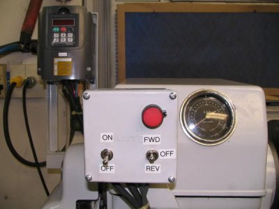
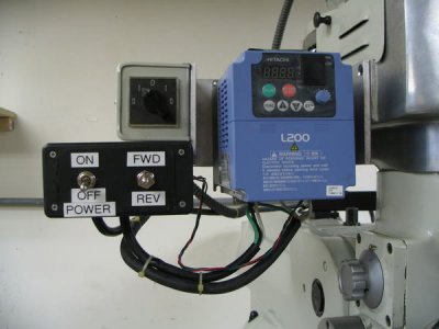
Heres a pic of my Sheldon lathe mounting, a Home Depot enclosure with the main power on/off sw, the fwd/off/rev sw and the pot mounted in it. The HuanYang VFD is mounted on a angle iron stand at the left back where it is easily accessed, but still out of the way. Also the mounting of a Hitachi on my mill, I use the pot on the unit here.

Sheldonfinished002.jpg
IMG_0619.jpg
 
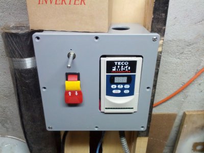
I pretty much added what you mentioned in the OP: a POT, and a master ON/OFF switch to cut input into VFD to turn it off at the of day:
IMG_20120809_224338.jpg

as an FYI - I drilled a 1" hole on top, and one on the bottom to allow fresh air to circulate in the box (hot air goes up, cool air comes from bottom) to prevent overheating of the VFD.

IMG_20120809_224338.jpg
 
An old mini-tower computer case turned so that the back is facing down will give you good ventilation and keep the chips out, especially if you replace the plastic front with a sheet metal panel.
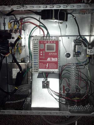
Here is the inside of one I am currently building:
2013-02-11_12-27-51_696.jpg


I have a fan in the middle that is ducted to the VFD to blow up and in to it. The black box at the top is a 240v to 12vdc power supply. The black master power switch, which will mount on the front cover is seen to the left right on top of the master power contacter.


2013-02-11_20-05-39_369.jpg
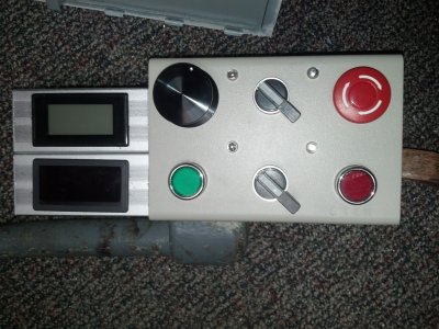
The displays on the left are for spindle speed and drive frequency. There is a knob for frequency setting, a switch for foreward/reverse, a emergency stop button, a start button, a jog/run switch, and a stop button. And, there are LED's to indicate the mode the switches are set to.

2013-02-11_12-27-51_696.jpg 2013-02-11_20-05-39_369.jpg
 
Thanks for all the useful comments and photos of the installations and enclosures. I have had a great deal of trouble posting photos on this forum, but I will try to post some of the installation of my Hitachi SJ200 on my Arboga drill press. I bent up and aluminum enclosure in the general format that twstoerzinger describes. I do have a cover that encompasses the removable control panel from the SJ200. This means relocating the little touch panel/LED unit to the outside of the enclosure.

The problem I have encountered is locating a suitable RJ45 female coupler (or connector) that is small enough to engage the male lug for the CAT5 connection on the unit. The couplers I have found are too large to enter the cut out of the body of the SJ200. Unfortunately, it seems that routers have deemed a lot of the older computer/network connection accessories redundant. Since the female sockets for the RJ45/CAT5 connections are most often affixed to a panel or bulkhead, the line connectors are bulky. I have not been able to locate a female socket to male plug on a cable; the scheme is always to use a female to female socket and then join the male plug in each end of the coupler.

I have done an extensive search on line and talked to some of the local computer service people with little luck. A local computer geek is trying to make up a "pigtail". He thinks he can source a suitable socket. We shall see. I will share what I learn. I called Driveswarehouse and they have been helpful in the past, but the comment this time was basically, "Any ethernet extension line should work." Obviously the industrial end users know something I (they?) don't.

Any suggestions are welcome. Thanks, Geoff Morgan
 
Geoff, am I to understand that the RJ-45 male is recessed in an opening? I do a good bit of network wiring, and can't recall an instance of that. Any chance of a picture of that? I have some pretty small bodied couplers, and would be glad to send you one, or perhaps you can change that connection to a more standard (as you pointed out) female jack. There are a few variants on standards for the jacks, and the trend currently is to shrink them into higher density patch panels. I'm doing some now that host 48 connections in a 2U panel. I hate them.
 
Geoff, am I to understand that the RJ-45 male is recessed in an opening? I do a good bit of network wiring, and can't recall an instance of that. Any chance of a picture of that? I have some pretty small bodied couplers, and would be glad to send you one, or perhaps you can change that connection to a more standard (as you pointed out) female jack. There are a few variants on standards for the jacks, and the trend currently is to shrink them into higher density patch panels. I'm doing some now that host 48 connections in a 2U panel. I hate them.

Thanks for the rapid response. I have a lousy photo. I think this is the solution: http://www.dalco.com/p-2552-cat5-rj45-inline-coupler-black.aspx
That coupler in the link looks as if it has minimal outside dimensions. The male plug is arranged upside down with the catch lug on the bottom which matches the socket; i.e. there is no cross connection it is pin for pin. If I can get the coupler to fit into the roughly 19mm X 16 mm (not counting the "arch roof" feature of the cut out) space, I can then rig a standard male to male patch chord to the little control panel.

The "male" end of the Hitachi RJ45/CAT5 is a little array of pins that engages the more standard looking RJ45 socket on the little control panel (the little panel simply snaps into place and automatically engages pin to pin). There is a little "doghouse" cutout in the body of the VFD (as described beforehand) that prevents the big "fat" couplers from Radio Shack/Best Buy/ etc. from engaging the coupler. I guess the manufactures of the current line of couplers has decided to make them large for visibility and easy for gorilla hands to deal with.

As an old geezer used to octal base systems for relays, tubes, etc., the current state of lack of compatibility is appalling. My son is an IT geek and I asked him. He said that routers have reduced the options for CAT5. I was shocked to learn that cross over cables use the same configuration as straight through wiring. That kind of insanity never would have been approved by previous generations of EE's and standards organization. Technology moving too fast for logic.
Thanks for your post and I welcome any comment you have. Geoff Morgan
 
Deleted. Again JPEG photo file nightmare.
 
Last edited:
Back
Top