What limits the speed of an air compressor?

Think of a river, the narrow spots the water moves through faster, then when you hit a wide area, it slows down. If it is the same river, it is the same amount of water flowing downstream in both conditions. Its just that the wide areas, act kinda like a small lake, and allow the water speed to slow down. And of course, the narrow areas the water needs to speed up to get the same flow.

Or think of a dam, the water above is calm, or close, and going through the dam, it is not a place you would want to be. Yet, both are flowing the same gallons per minute.

Do not think of flow (gallons per minute), the same as speed (feet per second)

Or some simple math. You are pushing 4 GPM. through the one pipe, you will still have 4 GPM. Now split it through 4 pipes, and you will have 1 GPM going through each pipe. And by doing that, the air speed through each pipe will be 1/4 of what it is going through one pipe. By going slower, you have more chance for the air particles to dissipate its heat to the pipe wall.

After all that, why do we still see single tube heat exchangers? I think it is the manufacturing cost. one long tube bent 50 times, or a ton of short tubes cut, and brazed to a ton of t'ees.

One long path, especially with a lot of elbows, will create internal friction. 1 you are pushing all the air through one tube, and 2, each elbow creates some friction. IIRC, for liquids each 90 deg elbow is equivalent to 1 to 2 feet of tubing. I do not know what it is for a gas.

Not trying to put the brakes on your project, it is a great idea, and I want to see the end game.
 
I'm glad you brought that up as I've been wondering about it. Almost all radiator/condenser/heat exchanger designs (and I've studied them a lot lately) have multiple parallel paths I can't figure why. I'm not arguing with you, or the designers of all these products; obviously you all know something I don't- just thinking out loud. To me, the only reason you cited that makes sense is less internal friction. In my mind, turning a zig-zag into a ladder would indeed slow down the air moving through, but now the air only passes through the cooling section once. Same amount of air passing through the same amount of pipe. Seems like nothing gained. If anything, it seems like the temperature outlet could be warmer, or least less of a guarantee of it being cooler, as turbulence/eddy effects might result in one of the parallel paths becoming a "preferred" path with most of the air passing through it and the others being less used. I have no idea if that's "a thing" but it seems plausible to me. With a zig-zag I wouldn't have to hurt my head thinking about it.

Maybe the gains in the cooling effect of multiple parallel paths is something not obvious? Some sort of exponential function or affinity law like the torque requirements of a fan rising with the square of shaft RPM?

If I seem like I'm pushing back at all, it's because I've bought a box of elbows, not tees, but mainly because I want to understand why I'm doing what I'm doing, whatever it is I'm doing.

Regarding radiators (heat exchangers), for a given flow (SCFM) capacity, a greater number of smaller diameter tubes improves heat transfer because, for each tube, more fluid (air) is coming into contact with the tube wall. Take for example a .375" ID tube; the area is about .11 sq in. and the circumference is about 1.18 in. Also, a 1.00" ID tube has about 7.18 times (.79 sq in) the area (flow capacity) but only 2.67 times the circumference (3.1416 in). Using 7 x .375 ID tubes (7 x .11 = .77 sq in) is almost the same area (-.02 sq in) but (7 x 1.18 = 8.26 / 3.1416) = 2.63 times the surface area inside the tube(s).
 
I made my aftercooler today. Between all my chores I didn't get a chance to tease any new numbers out of it, but at least it's there now. I decided to go ahead and move forward with my zig-zag design. I did not outright disregard the recommendation of multiple parallel paths; I was strongly considering it, too strongly. I was entering the analysis paralysis region and I had to slap myself out of it. I had a plan and I had the parts to accomplish the plan and just enough time to build what I had planned, so I built it. Thanks for the suggestions; please don't think I'm not open to suggestion. I am still planning on the wire wrap, even if not needed, just to see how much difference it makes. All I really need to do is get the air down to 140f; from there the air dryer can handle it. I ran it for a few minutes with a bit of restriction, time was growing short, no time for anything scientific, but coming out of the compressor the pipe was too hot to touch, and going into the air dryer it felt room temperature, maybe a little warmer. I think the unistrut frame it's mounted to sinks a great deal of heat, may not even need it's own cooling fan.


20200517_144256.jpg20200517_203038.jpg
 
I wanted to move the CFM gauge to the input side of the compressor for a few reasons:
1. It has a maximum pressure rating of 100PSI so with it on the compressor outlet as I had it, I wouldn't be able to connect any tools downstream of it, as the instant I stop using the tool, the gauge will be overpressured.
2. Measuring CFM @ specific PSI on the output is finicky. The tank introduces a lag; it's like a big capacitor. I set my flow valve to achieve a certain CFM and then I must watch my tank pressure for quite a while, see if it's going up or going down; am I drawing from the tank more than the compressor is replenishing? It can take a surprisingly long time to ascertain that. Am I drawing less than the compressor is replenishing? That takes time to determine as well. With the gauge now on the input I have an instant indicator of CFM.
3. I know that desired measure of CFM is the delivered air, that measured at the output as I had it initially, but nearly all consumer grade compressors are rated in SCFM at the input, as I have it now. My measurements now may not be as accurate, but they will be more comparable to published stats of competing compressors.

So I did move the gauge, and since i was fiddling with the intake I decided to rig up the silencer I had put in mind. I didn't even finish the design; I just got it to the point where I could draw air through it and through the CFM gauge. Despite this, the compressor is greatly quieted. So much so that I may even consider this good enough and leave it as is (at least for now).

20200518_152519.jpg20200518_155232.jpg20200518_155314.jpg


My plan was to have the bucket lined with sound deadening foam, and a few baffles through which the air must flow. But apparently just an empty bucket is pretty darned effective.
 
Finally! The Data We've All Been Waiting For...

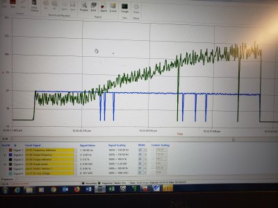
I screwed with the compressor all day in a fit of obsession, finally got what I wanted out of it. In what follows, there are some "screenshots" (cameraphone pictures of my laptop screen) of the scope graph spit out by the VFD software. The green Horsepower trace is very noisy because of the reciprocating nature of the compressor compounded by periodic sampling rate. It looks like crap but you can get the general idea. Also occasionally one or more values drop to zero; that's a bad connection of my USB>serial converter or a brain fart of the virtual machine I'm running, not sure which, but it doesn't mean the drive stopped; it ran flawlessly.


Here's what the HP looks like over a tank charge-up from 0 to 145 PSI with the motor running at a fixed 60Hz, as it would connected directly to mains power with no VFD. Green line is HP output, blue line is Hz (speed).

10020200518_225633.jpg


Here's what it looks like in constant horsepower mode. Again, Green line is HP output, blue line is Hz (speed).

00020200518_221746.jpg


Here is the actual data (no "approx") from both tests on one chart:

Capture.JPG


That is just what I had hoped the chart would look like; actually the results are better than I had hoped. I think my original math predicted 26CFM @ 0 PSI and something like 20CFM @ 40 PSI, but I knew real life would be much less. This is actually closer to the calculated values than it is to my gut feeling of what it would be.

That said, it turns out that the diminishing effect of higher CFM at lower pressures does not cumulatively amount to a whopping gain when you look at tank charge-up time. Here's the data on that:

Tank charge up, 0-140PSI (26gal tank):
Constant speed (60Hz) - 3min 21sec
Constant HP (120-60Hz)- 2min 26sec

Constant HP is 55 seconds (38%) faster.

I was hoping to fill the tank in half the time. Not sure why; that's obviously (now) stupid.

To put the above chart in some context, I've added some other compressors from the market:
1. Quincy Q13160VQ (3.5HP/60Gal/$850) 1589878536652.png
2. DeWalt DXCMLA3706056 (3.7HP/60gal/$779) 1589878981571.png
3. Campbell Hausfeld VT6271 (3.2HP/30gal/$599)1589879975053.png

1589879947055.png


Here's a video of a charge/discharge cycle if you're bored enough to watch. Feel free to criticize the unsafe disheveled lair; I've been in full-on obsession mode with this compressor and haven't tidied up since I started. Also it was a minor disaster before I started.


One important thing to note if anyone wants to try and replicate this: there is not exactly a "constant HP" mode in a VFD; at least not in mine. Maybe there is a VFD out there which has such a mode, but I don't know which one. When I was speaking before about constant HP, overspeeding the motor at lower amps, etc., I had maybe lost a bit of my mind. Drives typically have a constant speed mode and a constant torque mode.

Constant speed mode will hold the motor at (you guessed it) - a constant speed. Amps/torque can go up or down (within the envelope of the motor's nameplate parameters) depending on changes in load, but speed will remain the same - so long as the load doesn't get so great that it causes a high amps fault.

Constant torque mode will apply a fixed amount of torque from the motor. Hz/speed can go up or down (within the envelope of the motor's nameplate parameters) depending on changes in load, but torque will remain the same. If load goes down, speed will increase. If load increases, speed will decrease.

I set out thinking all I needed to do was put the VFD in constant torque mode, set base speed as 60Hz and max speed as 130Hz, and it would automatically behave as I had previously described. It turns out that that ain't how it works. The Yaskawa V1000 VFD that I used does not actually have a bona fide constant torque mode, but it does have a torque limit parameter which theoretically (I thought) should have allowed me to me to achieve an equivalent mode of operation: set a fixed 130Hz reference, and as it bumps up against the torque limit, the speed will decrease. It didn't. What happened was, above 60Hz in the region where available torque is diminished, it was still trying to match the sub-60Hz torque limit. It was trying to achieve nameplate rated torque at double the nameplate rated RPM. No bueno. Here's what that looks like:


Maybe if I had a VFD with a bona fide constant torque mode, the operation above nameplate rated RPM would have been handled automatically as I expected. It's been a long time since I've set up a drive in this manner. I really thought that above nameplate rated RPM they transitioned into a constant power mode. Pretty sure I didn't make that up. But whatever, I knew what I needed: A constant power mode, wherein speed and torque are variable, and it all works even outside the envelope of the motor's nameplate parameters. Since this drive didn't have such a mode, I made it myself. Yaskawa has two different softwares for their VFDs. "Drive Wizard Industrial" is what you saw in the screenshots above; that's the normal drive commissioning/parameter changing software available to anyone. But they have another trick up the sleeve: "DriveWorksEZ." DWEZ is a different, secret-but-not-quite-secret software that speaks to a different, secret-but-not-quite-secret processor on the control board. With this separate software, within this separate processor, you can do some custom programming; write some quasi-"PLC" type functions. Here's the function I wrote to achieve the "Constant Horsepower" mode:

00020200518_215245.jpg

Basically it does this:
1. If output power is greater than 125%, gradually lower speed (override commanded 120Hz speed reference)
2. If output power is between 100% & 125%, gradually raise speed (override commanded 120Hz speed reference)
3. If output power is less than 100%, return to commanded 120Hz speed reference

I bring all this up for 2 reasons; firstly to brag about my kludgey hack solution in the face of poorly made assumptions, and secondly to caution you to go into this better prepared than I did. Make sure that the drive you choose has some kind of constant HP mode which works above 60Hz, or that is has some higher-level programming function like DriveWorksEZ that isn't unobtainium. DriveWorksEZ is unobtainium. I would be remiss if I didn't point that out. They only want Yaskawa-certified techs wielding it. I used to work for a Yaskawa authorized distributor and I was a certified installer; that's why I have the software. You might not be able to get it. Don't just jot down a parts list from this thread and try to replicate it; it could be a costly disappointment.


OK... concept proven I think. Now that's out of the way, I can exit obsession mode and get on with my life, clean my shop, do the things I'm supposed to do. I am back to having a working compressor, even if a hideous abortion of one. I will come back and finish it in small bits as time permits. To Do:
- Weld up unistrut wonder, recover my hardware
- mount unistrut wonder (atop vibration arresting mounts), silencer, air dryer, tank, and an electrical enclosure, on a cart
- troubleshoot Quincy air dryer; may not be operating at 100% capacity
- Install analog pressure sensor, tied into drive or separate PLC. Wire up existing pressure switch as failsafe
- improve zig-zag heat exchanger, wire wrap, etc.
- finish silencer concept
- Install temperature sensors in key areas
- program other modes of operation, like re-charge
- Fabricate a metal shroud for it
 

Attachments

  • 00020200518_225633.jpg
    00020200518_225633.jpg
    535.8 KB · Views: 6
Last edited:
Amazing amount of time, effort and knowledge invested here.
Thanks for sharing it with us!

-brino
 
I agree, fantastic effort and report, thank you. Please do post the final configuration for our enjoyment too.
 
The only problem I have with this whole project is in use the compressor will run in a very narrow psi range. Does the cost of this conversion justify the apparent small increase in output? I was involved in compressed air systems for a major Glass container Mfg. we ran 3500 plus ( yep 3500) horsepower of compressors 24/7 to maintain the forming machines. I constantly looked at more efficient means of providing compressed air. Two methods stood out. One was to use a variable inlet controlled centrifugal machine as the system control. The other was my favorite but corporate didn't like the initial cost. It involved conditioning the intake air to the compressor by cooling & dehumidifying. This resulted in your choice of two results. One being a reduction of total horsepower or the other being is the increase of total air volume. Both gave you clean DRY air and reduced downstream treating of the air & maintenance to the forming machines caused by wet air. So to suggest an addition to your project, condition your intake air using a window air conditioner getting the air down to 30% humidity and 50/60 deg temp this set up should also pressurize the intake slightly also. I know this works I've seen it.
 
Very cool thread. Thank you for all the effort and data.

I used two "A" coils from a house central air unit, soldered together as my condenser. Yours looks really great too. One of my favorite simple formulas...P*V=P*V
 
Back
Top