What limits the speed of an air compressor?

If you don't know the channel, don't let the language fool you: he's a very clever guy.
I don't know, he runs the compressor backwards, talks about it as if it is a single piston compressor, Does not give me the feeling of clever.
 
I don't know, he runs the compressor backwards, talks about it as if it is a single piston compressor, Does not give me the feeling of clever.
He has his own kind of clever. If you watch more of his videos you'll see what I mean. Those things you pointed out, this isn't a good example. He's a jack of all trades, more knowledgeable in a vast number of topics than some experts are in only one.
 
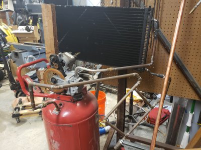
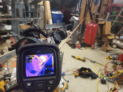
Well I have some data to present. Nothing on the topic that started this thread, but I am making progress. I haven't connected it to a VFD yet. I'm running it across the line off my 30HP RPC. I ran it probably an hour today, taking temperature measurements. I want to have an aftercooler between my compressor and tank; I had that on my old compressor and I don't want to give it up. My old aftercooler was an A/C condenser out of a chevy truck.

20200515_155938.jpg

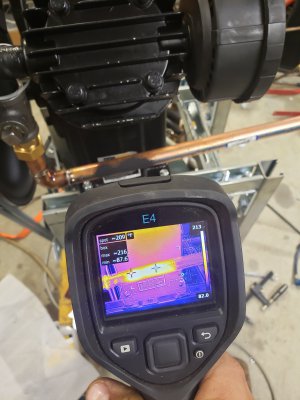
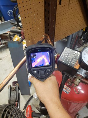
It was VERY effective but with only (5/16?") ID I think it would be too restrictive and throw off my numbers. I got some 3/4" copper pipe to make a zig-zag cooler but I wasn't confident it would be effective so before chopping my pipe up into a bunch of pieces I decided to see how much cooling 10ft of copper could achieve, by running it in a straight line.

20200516_181802.jpg

Turns out it drops the temperature by about 25deg in still air, and when I put a fan somewhere in the middle, it went to about 55deg.

20200516_183010.jpg20200516_183030.jpg

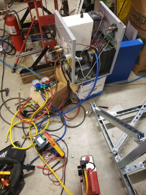
I think in a zig-zag with fan cooling across the entire thing, it might be just as effective as the condenser was. And this is just a pre-stage to an actual compressed air dryer (Quincy QRHT-25) that I got for free. It had suffered an instant death and instant replacement at one of the places I do work, and they were glad to have me dispose of it; I revived it (I think) and hopefully the only thing going into my tank henceforth will be clean dry air.

20200516_152555.jpg

I want to get all this in place before I start playing with RPMs, CFMs, VFDs, etc. Because the temperature of the air affects SCFM and I don't want to start the testing off with one set of control conditions and then switch it up, or have to re-do all my tests with & without the dryer setup. It's hard to hold back but I feel like if I'm going to do anything right here, I want it to be this.

Anyway, I don't have the dryer inline yet but I have some numbers, might as well post them

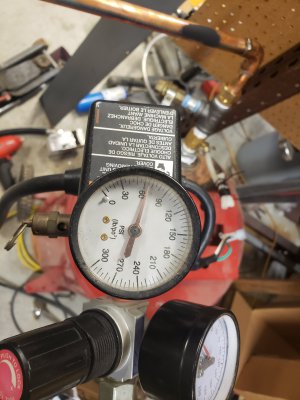
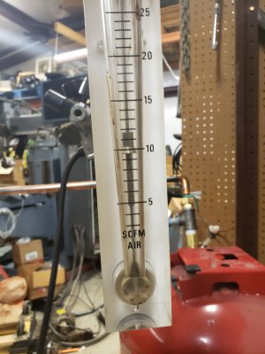
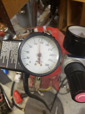
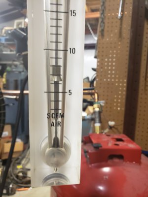
Here's what it Looks like at 60HZ across the line

20200516_182042.jpg20200516_182048.jpg
20200516_184639.jpg20200516_184645.jpg
At zero pressure it was about 14CFM I believe, didn't take a picture
 
Last edited:
Thanks for continuing to report. I’m following along and enjoying learning.
 
Be careful, the copper pipe you get at home Depot, or Lowes is usually the type M, I do not believe it is rated for compressed air. You want is type K.

You can increase the cooling ability by wrapping non insulated wire around the tube, to effectively give you fins. If the setups they use for hot water heating systems is type K, then they would be the ideal setup, they have the fins already on, just get the length you need, and solder or braze away (Not sure if solder is good enough for compressed air).
I'm using type K, rated 1280PSI. But even the annealed copper tube I believe was rated somewhere around 300psi. I don't know if you're referring to the "hydronic baseboard element" products with fins; I did think hard about buying a few lengths of that, but I couldn't bring myself to purchase anything else until I had verified that what I already have isn't going to cut it, and I think it will cut it.

Good tip about the wire around the pipe. I had wondered how effective that would be. I will test it. I really wanted to buy some of the "slinky" stuff that the pipe between the cylinders has wrapped on it, but I couldn't find that for sale anywhere. If you find it at all, it's wrapped on a pipe already and it's not something you just order a couple of feet of on Amazon; it's more of the "contact us for a quote; just let us know how many truckloads per month you need."
 
Yea, I thought the M was closer to the 150 PSI, been a long time since I read the charts. Thats why I had to look after posting that. The link is a good reading for anyone using copper pipe.

I was surprised at how much heat extraction you get with just a wrap of wire. I used a length of 6 strand copper ground wire. Another thing you can do, is use a couple of T'ees, and run two or more sections of pipe. Running them in parallel, is better then a longer single section. It allows the same amount of air to go through the cooler slower then in a single long section, and has less internal friction loss. Also, the air flowing slower, allows more heat to be absorbed by the pipe walls.

I'm glad you brought that up as I've been wondering about it. Almost all radiator/condenser/heat exchanger designs (and I've studied them a lot lately) have multiple parallel paths I can't figure why. I'm not arguing with you, or the designers of all these products; obviously you all know something I don't- just thinking out loud. To me, the only reason you cited that makes sense is less internal friction. In my mind, turning a zig-zag into a ladder would indeed slow down the air moving through, but now the air only passes through the cooling section once. Same amount of air passing through the same amount of pipe. Seems like nothing gained. If anything, it seems like the temperature outlet could be warmer, or least less of a guarantee of it being cooler, as turbulence/eddy effects might result in one of the parallel paths becoming a "preferred" path with most of the air passing through it and the others being less used. I have no idea if that's "a thing" but it seems plausible to me. With a zig-zag I wouldn't have to hurt my head thinking about it.

Maybe the gains in the cooling effect of multiple parallel paths is something not obvious? Some sort of exponential function or affinity law like the torque requirements of a fan rising with the square of shaft RPM?

If I seem like I'm pushing back at all, it's because I've bought a box of elbows, not tees, but mainly because I want to understand why I'm doing what I'm doing, whatever it is I'm doing.
 
Back
Top