Walking Beam Steam Engine

Hey Mark
Once again we are kindred spirits. Your method sounds great too. Also sounds like you have a good way to quickly locate the center of the rotary table and locating your part there. The center of my rotary table is Morse Taper 3. I have a set of MT3 collets, and in fact a lot of MT3 stuff because the tail stock of the lathe and the spindle of my mill is MT3. I have a bunch of little mandrels I have made for various and sundry things. I think I will start always putting a mandrel in a collet in the center of the RT and zero off that. Then mount the part to the mandrel. I do have to put the collet and whatever is in the collet in the RT before I bolt it to the table and I can't change it without unbolting.

Thanks for your post, glad you are making progress. What's next?

=<8^) Dave
 
Dataporter, mine also has a #3 morse taper as well but there was like a half inch gap at the top that allowed me to create a slug to fit in.. the slug actually has a step in it so that it can fit down into the morse taper bore as the overall height of the slug is about 1".

I've been thinking that for accuracies sake, I might eventually by a #3 morse taper adapter with a soft end on it. Machine it so it sits flat to the top of the rotary table and bore and ream a hole in its center to take the place of the slug I'm currently using.

Something like:

http://www.victornet.com/report/Arbors-Morse-Taper-to-Blank-End/1370.html

But a collet could do the same, hold a slug with a bore in it to hold the pin that aligns the part. The convenience of swapping alignment pins without having to remove the rotary table is what I'm after. But the fewer the number of slip fits the more accurate the setup would be.

I'm certain that there will be inaccuracies introduced by doing it this way. But if everything is fairly well machined and tight sliding fits that inaccuracy should be less then a thou especially if the sacrificial plate is kept as thin as possible. I still manually align the rotary table to the spindle using a test indicator and sweeping the top of the bore in the rotary table. I do put a 1/4" alignment pin into my mill machine collet and then align that pin into the bore of the slug to get the table real close real fast before clamping the table down. On Saturday, I was out about a thou on spindle to rotary table bore alignment when using this to to the initial table alignment.

The one thing would be that there needs to be an air hole connecting the alignment pin bore with the outside world so it can "breathe" otherwise one will simply create a tight compression fit that will push the alignment pin right back out. Course that could be a hole straight down the center of the alignment pin itself, it would have to be a very big hole, just enough to push itself back out. My current slug has a smaller hole drilled all the way through so this isn't an issue but it would be if I created a new alignment system with the #3 morse taper adapter.

If I can get an accurate setup I might just make my own #3 morse taper adapter.. it just has to be a short one - about an inch or so just enough to pick up the alignment.. hmm another project.
 
Had a great day in the shop today.
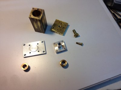
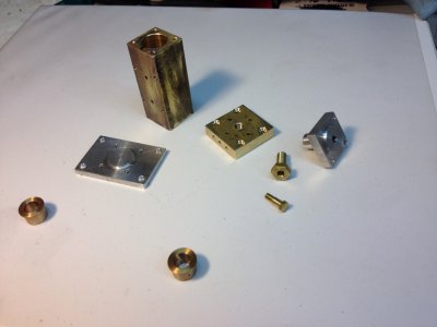
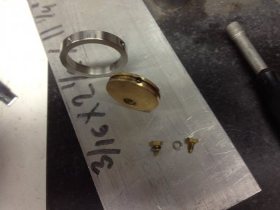
Here is a picture of some parts I completed last weekend and today. I had most of them already cut to size above, they are all but finished now.

Walking1.JPG

To give you some perspective, the brass Cylinder block is 3/4" x 3/4" x 1-13/16", the bore is .500"
The "Port Face" brass block is 1" x 1" x 1/4". The bronze "Main Bearings" for the pillow blocks are .250" ID.

Walking2.JPG

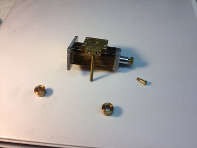
Assembled cylinder block on its side below (for some strange reason)

Walking3.JPG

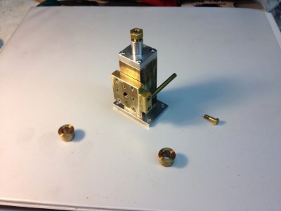
Assembled cylinder block upright below. Nice little 4-40 shoulder bolt, 5/16 hex head, 1/8 diameter shoulder for the small end of the eccentric rod.

Walking4.JPG

I think there is less than 10 parts I need to make now. Of course I still need to make the base... I need to hone/polish the bore a little more and then make the piston. Other than spring gardening chores, Honey Do's, etc, etc, this engine will be running soon!
I can't wait!

Walking1.JPG Walking2.JPG Walking3.JPG Walking4.JPG
 
Dave

Questions for ya - specifically on the Eccentric parts.

The book calls for a 6-32 set screw to hold the eccentric to the crankshaft. With the eccentric being only 3/16" wide and the groove cut in the middle of the part being 1/16" wide and deep, it seems that the 6-32 hole would be a bit problematic since the groove is meant for a 2-56 retainer screw to ride in. Suddenly you would wind up with the 1/16" groove all the way around with a ~0.116 hole in the groove. With what you've built to date, I see you've built the eccentric so I was curious as to whether you did as instructed, drilled and tapped 6-32 or whether you went smaller set screw such as a 2-56 as not to put a "funny" spot into that groove. Maybe I'm just concerned over nothing. The eccentric strap that runs on that will be fairly close (but free spinning) tolerance so perhaps there is no issue with it trying to slide off center alignment in that tiny space.

I also noticed in your picture you have some form of bolt in the place of the 2-56 retaining screw and another on the opposite side that would be in the hole tapped 4-40 for the eccentric rod. Is that just something you put in temporarily to hold the parts together?

I also noticed that in photographs of Rudy's original engine that the eccentric strap appears to have an extra hole at 90 degrees with a slight chamfer on it, perhaps an oil hole?? The hole doesn't appear to have a screw in it and doesn't appear on any of the drawings - and even the popular mechanics article calls for only the two opposite holes - for the eccentric rod and the retaining screw.

Finally what do you fellows do when a set of plans calls for a long length of really small diameter rod? The eccentric rod and one other rod are supposed to be 7/64" diameter, one rod is about 3-9/16 and the other 4-1/16" length. Finding 7/64" brass rod was somewhat difficult - I eventually found some on eBay - exactmetals, 2 x 1ft pieces for $1 plus $6 in shipping :) I added a few more pieces of stock since the price of shipping stayed the same. But curious how would one go about making such a piece if all one had was say 1/8" rod. Obviously without some kind of follower rest one would never be able to turn it in one piece and turning a shaft even in tiny segments would result in multiple sized shaft :) at least with this old boy at the controls. Does anyone have plans or an example of what a follower rest would look like for turning tiny shafts like this?

Sincerely
Mark R. Jonkman
 
The book calls for a 6-32 set screw to hold the eccentric to the crankshaft. With the eccentric being only 3/16" wide and the groove cut in the middle of the part being 1/16" wide and deep, it seems that the 6-32 hole would be a bit problematic since the groove is meant for a 2-56 retainer screw to ride in. Suddenly you would wind up with the 1/16" groove all the way around with a ~0.116 hole in the groove. With what you've built to date, I see you've built the eccentric so I was curious as to whether you did as instructed, drilled and tapped 6-32 or whether you went smaller set screw such as a 2-56 as not to put a "funny" spot into that groove. Maybe I'm just concerned over nothing. The eccentric strap that runs on that will be fairly close (but free spinning) tolerance so perhaps there is no issue with it trying to slide off center alignment in that tiny space.

If you look at the photo below, I believe I did use a 6-32 set screw in the eccentric. Not having 1-3/16 bronze on hand for the Eccentric strap, I made the eccentric itself from bronze and the strap from 303 Stainless... artistic license

I also noticed in your picture you have some form of bolt in the place of the 2-56 retaining screw and another on the opposite side that would be in the hole tapped 4-40 for the eccentric rod. Is that just something you put in temporarily to hold the parts together?

I decided to put two homemade 2-56 retaining screws with lock washers opposite each other and 90 degrees off from the eccentric rod... again artistic license

I also noticed that in photographs of Rudy's original engine that the eccentric strap appears to have an extra hole at 90 degrees with a slight chamfer on it, perhaps an oil hole?? The hole doesn't appear to have a screw in it and doesn't appear on any of the drawings - and even the popular mechanics article calls for only the two opposite holes - for the eccentric rod and the retaining screw.

I've noticed Rudy put a lot of oil holes in things that are not in the blueprints, artistic license? ;-)

Finally what do you fellows do when a set of plans calls for a long length of really small diameter rod? The eccentric rod and one other rod are supposed to be 7/64" diameter, one rod is about 3-9/16 and the other 4-1/16" length. Finding 7/64" brass rod was somewhat difficult - I eventually found some on eBay - exactmetals, 2 x 1ft pieces for $1 plus $6 in shipping :) I added a few more pieces of stock since the price of shipping stayed the same. But curious how would one go about making such a piece if all one had was say 1/8" rod. Obviously without some kind of follower rest one would never be able to turn it in one piece and turning a shaft even in tiny segments would result in multiple sized shaft :) at least with this old boy at the controls. Does anyone have plans or an example of what a follower rest would look like for turning tiny shafts like this?

I looked all over creation for 7/64" ANYTHING! I did discover I have some 7/64 drill rod that I will use to make these two parts. Not finding that, I was going to use 1/8" and modify the thread on the parts to 5-40 thread instead of 4-40 or just cut the ends of a 1/8 rod down to .109 to thread them 4-40..

Trying to cut a rod that small that long with a lathe is beyond my skill set. You could make a tool like they use on automatic screw machines with roller bearings on one side and the cutter on the other. I don't have enough time left to mess with something like that, why make rivets when you can buy a box for two bucks? Now, if you have a centerless grinder laying around... (just kidding!)

Always great to hear from you, Mark! I've been building a goll darn chicken coop instead of working on this engine! Soon I'll be on the Chicken Coop forum!

Best Regards! Dave
Walking6.JPG

Walking6.JPG
 
Thanks for the response Dave

Artistic license is a good explanation :)

For the bronze eccentric strap I went out to Amazon and did a search for a bronze bushing that had a large OD and a smaller ID then I needed and picked one up for like $3.50 with free shipping with Amazon Prime. It wound up being 3" long so I can make multiple attempts if I need to :) Buying a solid piece of bronze or even a 13" long cored bronze (Enco) was too expensive for that small part. To be honest, I was doing a search on Amazon for Bronze and the search results came back with bushings in it, and when I saw the price, I knew I found a cheaper route to get the size and amount of bronze that I needed (lest you come to the false conclusion that I was smart enough to search for a bronze bushing to begin with).

The eccentric rod could easily be done at 1/8" with the end turned down and threaded 4-40 with no issues (otherwise need to adjust the eccentric strap), it just a "connecting" rod between the valve and the eccentric. The piston rod on the other hand has to be 7/64" *or* one has to adjust the top cylinder cover and gland accordingly. I'm sure drill rod would suffice there.

I went ahead and started making the parts last night, hopefully I'll finish up the eccentric tonight.


mark
 
Dave

I was wondering about one other thing - the "upper cylinder cover". I noticed you made yours square to match the shape of the cylinder and Rudy made his round. In Rudy's model he put a rolled sheet metal shield around the cylinder, yet the book doesn't include a drawing of that part and even in the Popular Mechanics article its barely alluded to. In one photograph where the shield is missing it states: Thin sheet metal is rolled in a sleeve to form an insulating lagging or cover around the cylinder. Most of the closeups don't have it. I assume it might provide some insulative effect around the cylinder on a "hot" engine possibly preventing early condensing of the steam but I wonder how important it was or whether it was more or less a cosmetic feature to make the cylinder look bigger then it really was or round vs square. I assume you've dismissed it as a necessary part since you altered the upper cylinder cover to be 3/4" square. I think if I were to remake the engine, I might have actually considered making the cylinder out of 1-1/8" round rod and milling a flat on the one side to bolt the port face to. To be honest that would have been cheaper then the chunk of 3/4" square brass I bought (mostly because I had some 1-1/8" round, and for whatever reason round stock seems much cheaper then square or rectangles).

Its funny I never think of these things until I'm part way through the project and already created most of the parts in question including the round upper cylinder cover. Maybe its just my first engine so I take everything at exactly face value when I start instead of critically evaluating the parts. But then again I know Rudy was probably 1000xs more of engineer and machinist then I will ever be. But I'm also guessing at least some of his designs revolved around materials he had on hand along with possibly in field adjustments - adding oil holes perhaps or finding them unnecessary. I guess someday I'll learn what I can change and what I can't without resulting in negative consequences on the running of the engine.

I'll probably plow through a few more parts this week. I just came off of 6 months of working 6 days a week - 10 - 16hrs a day. It really feels weird to only be working 8 hrs a day, I'm like totally lost and sort of panicked, as they let my boss go last Friday so I don't know whether I will soon be unemployed. But for the time being, I'll enjoy the slowdown and play out in the shop and try to learn to be less cranky around my wife and kids. I'm off to Cabin Fever Expo in York, PA this coming weekend.

Sincerely
Mark R. Jonkman
 
Hey Mark
I'd sure like to go to Cabin Fever someday, let me know if I should put it on the bucket list. Went to Dodger Stadium for opening day last Friday, so I have a slot open on the BL.
Hope you keep your job but not have to work so many hours...
Finding or modifying existing bushings is a great way to create bearing bronze parts!
I was thinking the round cover on the cylinder was more for looks than anything. Maybe to make it look bigger in relation to the other parts for aesthetics. I was setup for the 3/4 square to finish the ends of the cylinder to length and I had the 3/4 square aluminum, so I elected to make the top cylinder cover while I was at it. And if I had not found my piece of 7/64 drill rod, I would have made the gland and top cover stuffing box a bit bigger to accommodate a bigger piston rod.
I think on my first couple projects I might of stayed closer to the plans, just so I didn't get to the end and say, "Uh-OH!".
I prefer READY, AIM, FIRE! to any other order of those three words!
Take Care

Dave
 
More Progress on My Walking Beam Steam Engine

Well, after not making much progress on my walking beam engine because of spring chores and of course, the chicken coop, today I made some real headway.

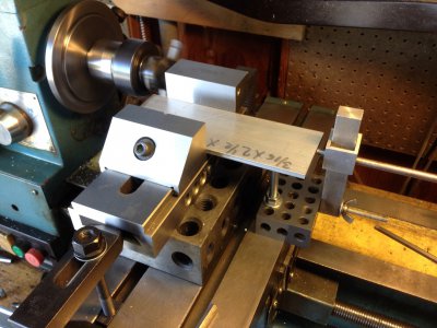
I made the aluminum base. Below, I am using a fly cutter mounted in the lathe spindle to cut it square and to final size with a nice finish on the ends:

Walking7.JPG

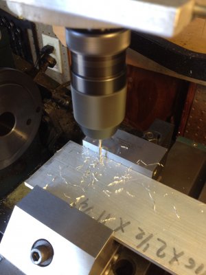
And since I am using a 3 in 1, I used the same setup to drill the holes required.

Walking8.JPG

I also cut the connecting rod and the five 1/8" pins that go through the beam and all the links. I used some stainless steel rod for this. I used a hack saw to cut them and then used the bench grinder by hand to get them to length and put a nice finish on the ends.

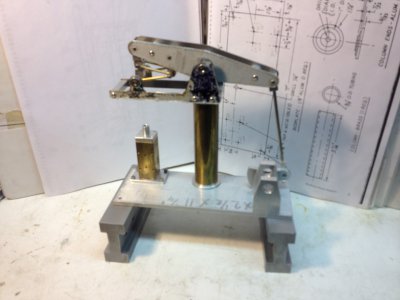
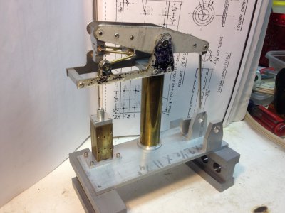
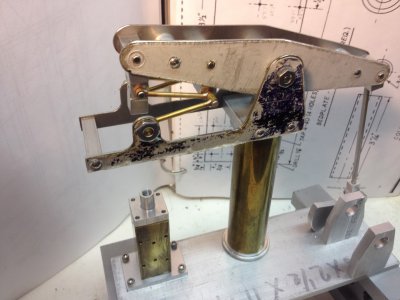
So, having the base done, I decided to do some trial assembling. Here are some pictures:

Walking9.JPG
Walking10.JPG
Walking11.JPG

The action of the parallel links and all the associated links and parts is poetry in motion!

Here is what I have left to do:
The wood base
The crankshaft
The eccentric rod
Finish the steam inlet flange
The valve pivot
The piston rod
The piston
Make the gaskets
Lap the cylinder block and the port face
Final tweaking
Polishing, etc.
Final assembly.

I'm looking forward to pulling that protective plastic cover off the stainless steel spring beam and walking beam!! It looks ugly, but I don't want to risk scratching it until I'm done with everything.

I'm also getting to where I can't wait to see it run!!!

Walking7.JPG Walking8.JPG Walking9.JPG Walking10.JPG Walking11.JPG
 
Thats looking really good Dave!

I'm starting to catch up to you :) I have the linkages and parts up for the ends of the beam and then the intake and exhaust fittings and I'm pretty much done except for getting to run. Which brings me to the next question I have for you. What do you use for packing - I assume under the gland there needs to be some packing to seal the space between the piston rod and the gland hole. I used an o-ring for the piston but not sure what to use for packing under the gland (assuming I'm correct that there needs to be something there).

Sincerely
Mark R. Jonkman
 
Back
Top