Victor 1340GHE, New to Me

David2011

H-M Supporter - Gold Member
H-M Supporter Gold Member
Joined
May 19, 2022
Messages
391
This discussion started in the brand specific area before I found the lathe. It continued in the "All About Electrical Issues" and now to this more general interest area.

One of the early discoveries was that the lathe absolutely puked oil from the chuck end of the headstock at the spindle. I found a Woods Creek Workshop video of his Jet 13x40 headstock overhaul about 3 years ago that was very helpful in knowing what to expect in the way of partially removing the spindle and how the oiling worked. The Jet is not identical to my Victor but it's close enough that there were no surprises. The oiling "system," if it can be called a system, was the same; sling and drip.

Before opening up anything I removed the chuck. Clearly this lathe was owned or operated by a gorilla, both strength wise and mentally. I had to use a 1/2" drive 20" breaker bar and a socket to break the QCTP nut loose and a shorter 3/8" breaker bar to break the camlocks free. Once the chuck was off of the spindle I checked the runout inside the MT5 taper. Finally, there was good news. The runout barely moved the needle on the DTI. It was no more than .0002".

After taking the top off of the headstock I found a significantly overfilled reservoir with the oil going well above the top of the sight glass. The high oil level was no surprise since the sight glass was cloudy almost to the point of opaque. The gasket behind the bearing cap was also leaking. The former operator still had surprises in store for me. When I went to remove the locking nuts from the left end of the spindle they weren't there. I hadn't even noticed until that moment. The tension of the bearing around the spindle was all that was holding it in place. Then I noticed that there was no screw and washer in the middle of the pulley for the belts from the motor. Fortunately, the screw is a hardware store item and the bearing locking nuts were available with overnight delivery from Amazon.

I scraped the paper and blue silicone sealer off of the surfaces and cleaned them first with mineral spirits and then acetone in preparation for some Permatex Gasket Maker. The rollers in the bearings are no longer shiny and the races are showing some dulling of their shine as well but with the minimal runout I'll wait a while before replacing them.
 
The spindle went back into place easily. The chuck end bearing cap was bedded with the black oil resistant Permatex and tightened per the instructions. Later, the outboard bearing was heated with a heat gun and slid on easily. The second bearing cap was bedded with the same Permatex. The bearing lock nuts from Amazon fit perfectly. I snugged the bearing to set the preload, shooting for around 16 ounce inches of resistance. A trigger pull scale and some no stretch fishing line made measuring easy; 16 ounces of pull on a 50mm/2” OD spindle; radius = 1”. The full set of spanner wrenches that I got recently (inexpensive and handy) made the adjustment and tightening the second nut against the first one a piece of cake. So far, so good.

Hindsight is so awesome! Foresight would have been even better. The speed control on this machine is like that of many Colchesters with two rotating levers. I only had to disconnect one of them to move the spindle. It didn’t occur to me how difficult it would be to correctly index the shaft and its gears to make the power transfer gears align correctly and in sync with the detents on the lever. A few dot of paint marker would have made all the difference.

Headed back to the shop to try and figure out the magic combination to make it shift speeds correctly.
 
Last night, as I wrote, was challenging as I tried to reassemble the speed selector. At a point I turned the shaft 180 degrees just to see if I had put it back in wrong. As I tapped the roll pin through it came to a HARD stop. After struggling with it for about 3 hours I finally got it, pulling it with Vise Grips while twisting and prying upward on the pliers with a screwdriver. Upon inspection it appears that the cross drilled hole in either the shaft or the slider arm was off center just enough to prevent the roll pin from going all the way through when the shaft was turned 180 degrees. Once the roll pin was out I quit for the night.

There’s something to be said for old sayings. “Insanity is doing the same thing over and over and expecting a different result” comes to mind. I had been driving the back roll pin out; the one in the back that engages the slider arm. Then I was moving the shaft rearward just far enough to clear the gear that drives it, rotate a tooth, reassemble and try again. Over and over and over. Same results every time; one or two positions would align the gears an the others didn’t.

Today I tried a different approach. I left the back end of the shaft pinned to the slider arm and punched out the front pin. I aligned the slider with its gears with the front gear pulled away from its mate on the speed control lever, made sure the lever was in its detent, moved the gear back into position where it was aligned with the hole in the shaft and pinned it. Finally, the spindle speed gears aligned properly when the selector hit its detents. I never imagined that aligning what appeared to be a simple system would give so much grief.

After I was convinced that the alignment was solid the top cover of the headstock and the mating surface of the headstock were cleaned, Permatex applied and the headstock was buttoned up. I let the Permatex cure for several hours before running the lathe. After a run at all speeds I chucked up a piece of brass stock, faced it with the power cross feed and knurled it as a test for some parts that I have to make. I didn’t see any oil leaking from around the bearing cap where it was puking oil before. Stopping that oil loss was the entire point of the work.

Satisfied with the success, I enjoyed an Old Fashioned and caught up on some TV binging with my wife and dog.
 
Last edited:
Too many words and no pictures. Sorry; I have to sit down in front of a real computer to use the software I like for manipulating pictures for posting.

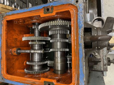
IMG_6194.JPG

After disconnecting the shaft and removing the speed selector gear but before doing anything else. The small gear center-right drives a larger gear that mounts on the shaft that's partially removed. The headstock had about 20 ounces too much oil when I got the lathe.

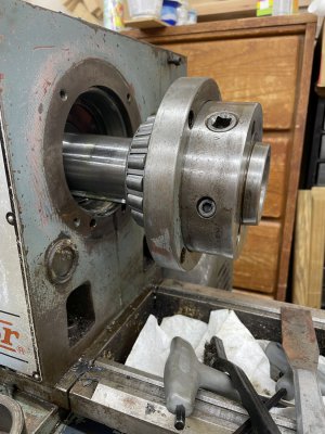
IMG_6193.JPG

Bearing cap removed, bearing was heated with a heat gun and the spindle driven out with a wooden block and a hammer. It tapped out pretty easily after heating for 7-8 minutes.

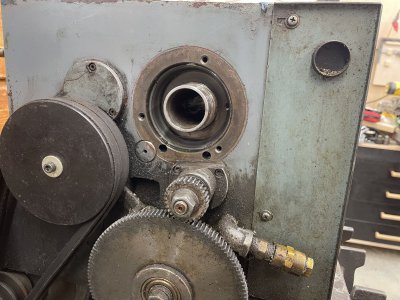
IMG_6195.JPG

With the spindle moved out from the headstock I cleaned the old gasket off, degreased with mineral spirits and then acetone on just the bare metal. The paint softened immediately on contact with acetone so I tried to avoid getting any on the paint. A trickle of oil can be seen at the center of the spindle hole. I think the oil discharge during and after running the lathe was due to both too much oil and failed gaskets. Someone had tried to Band-Aid the leak with an external application of blue silicone sealer which didn't work. After owning sailboats for almost 30 years I'm a firm believer in taking things apart and thoroughly cleaning them before attempting to re-seal.


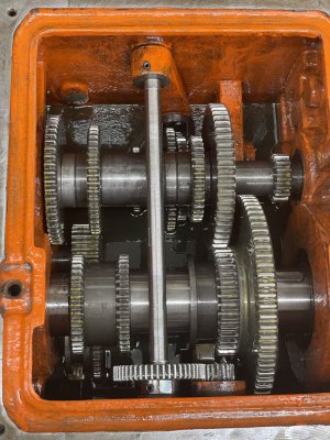
IMG_6198.JPG

Insides of the headstock after reassembly. Note that the roll pins at the slider arm and the gear on the shaft are not aligned. That complicated my understanding of correctly re-installing the shaft and gear to get the speed gears and detents in sync.
 
Last edited:
Thanks for the photos! I'm like a child, and love the visuals. Those Victor lathes got some real metal in them. It's a pleasure following your project!
 
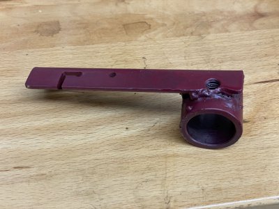
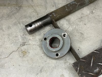
The foot brake had to be adjusted before the VFD could be set up to cut power to the motor. The lever inside the left cabinet was wobbly. When I tried to tighten the bolt it became obvious that it needed more than an adjustment. The bolt was diff to remove all the way out and once out, most of the threads were missing. The lever had been broken off of the tube that connected it to the foot brake shaft. It had clearly had been repaired by “Bubba” in the past. After re-tapping the threads a replacement bolt helped align the pieces and the welding machine’s ground clamp served as an alignment clamp. There had been little penetration from the original welds so I made sure to linger as long as I dared to get good penetration. A little file work and one more pass with the tap and it’s ready to install. I’ll take pictures before putting it back together.
 
The foot brake repair came out very well. While the paint dried on the repaired piece I cleaned the bushings and screws that hold the brake pedal in place and installed the brake pedal. A third hand would have been nice trying to maneuver the brake arm back onto the brake pedal shaft while attaching the brake cable and retraction spring all at the same time. Everything lined up after a little struggle and the brake arm slid home, thanks to thorough cleaning and greasing of the mating parts. A new 8mm hex head capscrew and lock nut were installed and the brake is as good as new.

IMG_6202.JPG
Repaired brake arm. The welds aren't beautiful and I had the heat a little high but I think I got better penetration than the original welds.

IMG_6201.JPG

The brake pedal shaft and bushings were cleaned and greased and the shaft was deburred for easier reassembly.

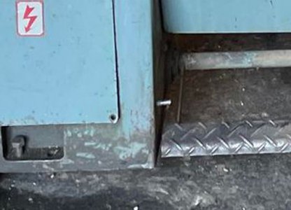
Foot brake before repair.JPG

Brake pedal before repair. Note how far it sags below the stop pin.


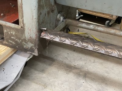
IMG_6205.JPG


After the repair the brake pedal comes up to the stop pin. The pedal only travels a short distance before fully engaging the brake.

IMG_6206.JPG


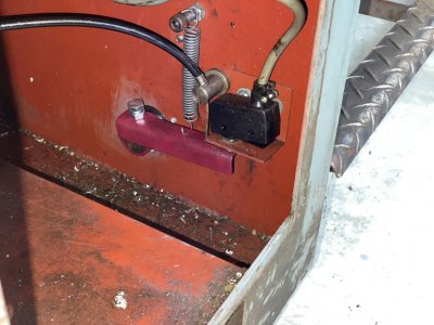
Unfortunately I was fresh out of red lead primer so garish red had to do. Inside the base the relationship between the brake arm, retraction spring and switch is easily seen. It's been a very long time since anyone cleaned this machine.
 
"Phase One" is completed. The electrical functions are all as I wanted them with speed control enabled at the VFD, the foot brake is working in conjunction with the VFD and the spindle control lever controls the spindle through the VFD. This is a 1988 model machine and I was pleased to find that every original equipment electrical component I researched is still a current production item. The lathe has a good range of speeds available just by moving a lever or two but the VFD will be nice to fine tune the spindle speed as needed.

The lathe was pretty noisy at higher speed settings, just like my smaller change gear lathe that howls when I get the banjo gears too tight. After degreasing the banjo gears, applying fresh grease and setting the gaps with 2 layers of copier paper, the machine is reasonably quiet all the way to its maximum of 2000 rpm. Runout inside the MT5 taper and on the D1-4 alignment cone is negligible. The dial test indicator needle just vibrates a little on both tapers, not even moving .0002".

There is still a lot of cleaning and possibly painting to do and I'm sure plenty of fine tuning left but I can now move it into its place and level it. ---And USE IT!
 
Preparing for Paint

Almost 3 weeks later I still haven't put the lathe in its permanent space. I decided to paint it since it's so much easier while it's on dollies. This post is mostly about degreasing. I'm not sure that's the correct term when some of the deposits were rock hard oil with metal chips embedded. Unfortunately I was unable to take photos because I didn't care to touch my phone with all of the crud on my gloves. You do not want to use this product without gloves!

ZEP has their Industrial Purple Degreaser that caught my attention at Home Depot. The hype in the label seemed to indicate it as their product intended to clean machinery so I bought a gallon. Before I started using it I searched through YouTube to see if there were any decent videos on the degreaser. One was a blacksmith that had a power hammer that he bought freshly restored and had never cleaned it thoroughly since. He had some great tips including using it at the recommended dilution of 1 part to 5 parts water for heavy deposits. Another was to follow the instructions and let the applied area soak 3-5 minutes per the instructions.

If the dirty area is just mildly greasy/oily, this product will wipe it off on the first pass. My lathe had probably never been cleaned. Deposits inside the belt guard were up to 1/4" thick and had the consistency of asphalt. The motor's fan cover was pretty encrusted as well. Those items got a lot of soaking in a stainless steam table tray. With periodic brushing, all of the hard deposits eventually (within an hour or two) came off. There is a warning on the label to not use it on painted surfaces but other videos indicated that indoor house paint can be removed with it but it was OK on oil based enamel that is fully cured. The label also warns to not use it on chrome. I ran across several videos showing people removing "chrome" with the ZEP degreaser. They were all removing"chrome" from plastic parts which in reality was more likely an aluminum ion vapor deposition as seen on plastic car model "chrome" parts. A significant component of the degreaser is sodium hydroxide which can disslove aluminum. I cleaned some chrome plated steel screws, letting them soak from the time I removed them until after I had cleaned all of the bigger pieces and no damage was done. --Try this "in a safe area" for yourself before trusting what I've written.-- All I can say is how it worked for me. It might no be as kind to newer eco-friendly coatings.

I cleaned all painted surfaces of the lathe with the ZEP degreaser. Some areas cleaned up with a single attempt; others requires multiple tries. I felt like it was every bit as effective as a petroleum based product without being flammable. I'm not afraid of volatile solvents but the ZEP product is far less costly and doesn't evaporate quickly. Once the lathe seemed clean I degreased one more time. A final wipe down with mineral spirits will be done before I start painting.

The paint I chose is Majic Paints Light Ford Gray; the same color as every antique Ford tractor out there. They also offer a catalyst/hardener that is intended to increase the gloss and hardness but unfortunately it also causes the paint to dry/cure more quickly. I hope the faster drying time doesn't affect the flow out time. It came from the local Tractor Supply. The mix ratio is 1/2 pint of catalyst to one gallon of paint so I'll mix 16 ounces of paint to one ounce of catalyst and see how far I get on the first batch. I'll be rolling and brushing it onto the lathe. The entire lathe will be ready for paint before I mix any so none should go to waste.

Originally the dark red International Harvester Red appealed to me but after degreasing and realizing that painting everything that was originally gray with red would require far more disassembly than I wanted to do. The red was returned and exchanged for the light Ford gray. If there's a lot left, and I expect that there will be, I'll probably paint the mill with the gray as well. If I use a large portion of the gray, I can still paint the mill red. There's no original paint on the mill that's in good enough condition to worry about.
 
OMG!

While prepping for paint I reluctantly decided to remove the coolant pump and tank so it could be cleaned and painted on all sides as well as painting behind it. On this machine it attaches to the stand that’s beneath the headstock. As I started removing the bolts it felt like it was much heavier than it should have been. Not a total surprise since chips were backed up into the formerly clear vinyl tube that returns coolant to the tank. Once it was free I removed the drain plug but only a few drops of clear but vile smelling water came out. That was odd, I thought, since clear gold colored cutting oil was visible through the return hole.

When I poked a screwdriver into the drain more water came out. It reminded me of the odor of digging up stagnant pond mud combined with crude oil. Lovely! At the same time it was obvious that chips were firmly packed in the tank. In spite of having a container in place, when I started breaking up the mass of chips with a big screwdriver water and oil started flowing at a rate beyond what I had envisioned. Whatever you’re imagining right now is probably correct. The oil coming out of the drain was nothing like that visible at the top of the tank. It looked like thin crude oil, very black and not much more viscous than water. After getting the drain plug back into the drain, which of course got stuck momentarily while oil continued to seep, it was finally sealed.

I cleaned the oily mess off of the floor and the tools and called it a night.
 
Back
Top