VFD for Rong Fu mill

Here's the full motor control wiring diagram for my Griz G1007/RF-30 mill (with the Teco FM-50 VFD). The 510 would probably be wired similarly. You can set up the VFD to either use "Run forward. Run reverse" switches -or- as in my case "Run, Forward/Reverse" switches. Note that I made use of the original on/off pushbuttons on the mill for the "Run" function - just rewired them to low voltage inputs to the VFD. My fourth photo above shows the original pushbuttons, with an added "safety stop" paddle to activate the "Stop" button. By the way, you should NOT place anything between the VFD and the motor.
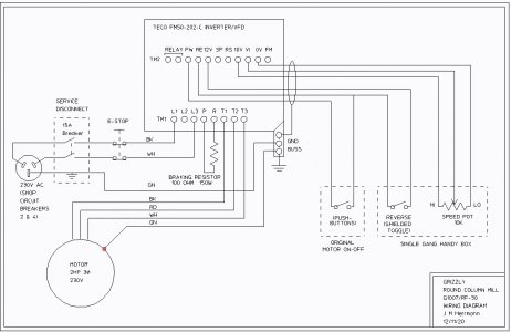
Skee-matic 0C11.jpg

Given that your single phase motor is 2HP, any 2HP (or even 1 1/2HP) three phase motor should work. Who knows ... to get the proper shaft size, you might even have to find a 3HP motor. You can run a 1 1/2HP motor with a 2HP VFD, but for a 3HP motor, you'd have to go to a 3HP VFD. Worst comes to worst, you can always chuck the pulley into your lathe, bore out the hole, then add a keyway. Just don't try to drill out or ream out the pulley bore. The existing keyway will cause all kinds of problems, and the hole will end up off center. I was about to do that with the pulley for my new mill, and a "real" machinist friend strongly cautioned me not to. [I don't consider myself a real machinist - just a tinkerer who also does machining :) ]

Even easier would be if the motor shaft is smaller than the pulley bore. Then it's just a matter of turning a bushing (with a slot added to clear the key). The 2HP motor I used had a 7/8" shaft. If your pulley has a 24mm bore (0.9449"), this is what you would do.
 
I modified a motor I installed in my lathe that had the wrong size shaft. I removed the rotor, and machined it between centers on the lathe, and made it fit the original pulley.
I do not recommend the low cost China import VFD. You want it to be of the "sensorless vector" type. This will allow high torque at lower RPM. Also this will have a feature that enables the normal Hz display to display RPM of the spindle. This is done by inserting the constant ratio of motor RPM to spindle RPM in a programming location (scaled output frequency), and then have the LED display show this (Teco FM100, Hitachi, Mitsubishi support this, the TECO L510 does not). I have this on all my tools. I've removed single phase motors from all shop equipment, and install 3 phase mostly from eBay used. But some as a motor package from dealerselectric of motor and VFD.
 
I have 3phase with VFD on my Rockwell gear head mill and it is a rock! I have a 2 HP (advertised as) treadmill motor I bought from surplus center years ago along with a control board. I have modified at least 7 of these with the MC60 control to eliminate the slow start and let you turn it off and back on at the same speed. It is less than optimal on my lathe, although it does give me a tremendous speed range with a 6KRPM motor. It has a tendency to bog down on some things and is a bit frustrating. I have a true 3/4HP 3 phase with VFD to install on the lathe as soon as they let me back out in the shop. I had a heart attack and they replaced to fuel lines and did a valve job on me. Feel like a new man :)
 
So a few clarifications:
1. As far as a motor replacement, you have a metric motor and the replacement with the same size shaft would be the Metric D90L motor frame in a 1750 RPM (4 pole) 2 Hp motor. The Leeson motor previously mentioned should be close to what you have, but until you measure up all the dimensions on your motor I cannot confirm. Marathon also makes a metric version in 3 phase, often it may be the same motor with a different badge. The Leeson motor is inverter rated, so would be my recommendation. You may need to drill new motor mounting holes in the mill mounting plate.
Leeson Metric Motor, D90L, 192205.00
Zoro often has promotions for 15-25% off, sign up for email and you should get 15% with free shipping.

2. On the VFD, many mill owners go with the Teco L510, it works well without being too expensive. It does not have an external braking resistor and has somewhat limited programing features, but works well enough. One normally does not use the scaled RPM display on a mill because it only applies to one belt ratio. The L510 display can be scaled to a different RPM range than the motor, parameter 12-03 can be scaled to the spindle speed instead of the motor speed, and will change RPM proportional to the Hz change. There is also a 0-10V analogue output that can be scaled for speed, but takes some fiddling to get it all worked out. There various other ways to display speeds, but an inexpensive tach with a magnet attached to the spindle is usually the easiest on these types of machines. AN external tachometer does require a power source, usually 12VDC at maybe 50 mA. The Teco L510 has an internal braking resistor but no outputs for an

You will want to do a static auto-tune once everything else is done and running correctly. This is described in the manual and tunes the VFD to your particular motor.

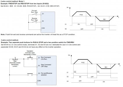
3. There are two basic control methods for the run commands, they are described on pages 4-32 and 4-34 of the manual. The first is 2 wire control (mode 1 in the manual), when the COM terminal is connected to S1 it is the Forward command, when connect to S2 it is the reverse command. This requires a sustained signal so typically you use a 3 way rotary switch with the center is no connection = OFF. The second method is called 3 wire control, and uses momentary buttons, stop is a normally closed switch and run forward is a momentary normally open switch. When the run switch the is momentary closed, the VFD will go into a run mode even after the button is released. It will stop when the stop button momentarily pressed which breaks contact to S2. If you want to have the mill run in reverse, then you need a separate sustained switch that connects COM to S3. This signals the VFD to run in reverse, but it still needs the RUN command to start. If the VFD is running in the forward direction, and you switch on the reverse switch, the motor will decelerate to ) RPM and then accelerate then run in reverse.

If you hook up everything and the motor is running in the wrong direction, then disconnect the power to the VFD and wait at least 5 minutes for the capacitors to discharge, then switch any of the two motor wires at just at the motor OR VFD not both.

2-Wire Control
3 position Maintained switch use with two NO switch blocks, center position neither switch block is closed
Legend Plate
Forward-Stop-Reverse

3-Wire Control
STOP Command NC Momentary Switch https://www.automationdirect.com/ad...inated_pushbuttons_flush_-a-_extended/gcx1111
RUN Command NO Momentary Switch https://www.automationdirect.com/ad...inated_pushbuttons_flush_-a-_extended/gcx1102
Reverse Switch 2 position Maintained https://www.automationdirect.com/ad...d_-a-_non-illuminated/non-illuminated/gcx1300
(forward the switch is open, reverse the switch block is closed
Legend Plates
RUN https://www.automationdirect.com/ad...button_accessories/legend_plates/ecx1670a-b09
STOP https://www.automationdirect.com/ad...button_accessories/legend_plates/ecx1670a-b11
Forward-Reverse https://www.automationdirect.com/ad...button_accessories/legend_plates/ecx1670a-b13

Speed Pot. 5K https://www.automationdirect.com/ad...dicators/22mm_metal/potentiometers/ecx2300-5k
Speed Scale https://www.automationdirect.com/ad..._indicators/22mm_metal/potentiometers/ecx2640

E-Stop https://www.automationdirect.com/ad...ttons_illuminated_-a-_non-illuminated/gcx1131
(E-Stop comes with one NC switch block, when pushed it breaks the COM signal going to 2 or 3 wire controls, a second NO switch block can be used to connect the COM to input S4 that can be programmed to signal a Rapid Stop,Parameter 03-03 = 14:Rapid Stop (Decel to Stop).

If you decide to get into it I can assist you with suggested parameters.

VFD COntrol 2-wire vs. 3-wire.jpg
 

Attachments

  • L510_instruction_manual.pdf
    4.7 MB · Views: 2
Thanks for the link to the manual. This new one looks better illustrated than the cartoon-like style of the FM50 manual. Interesting that they no longer support a braking resistor (except in the 460 volt models). Make me wonder how fast the motor can safely be braked.
 
Thanks for the link to the manual. This new one looks better illustrated than the cartoon-like style of the FM50 manual. Interesting that they no longer support a braking resistor (except in the 460 volt models). Make me wonder how fast the motor can safely be braked.
I see many posts where hobbyist's install braking resistors. They are not needed. In industrial application where there is a huge inertial load, they may be part of controlling the speed, especially if gravity starts accelerating a conveyor, for example. The VFD will decelerate to stop, and DC injection braking can be enabled. But I typically set my VFDs to "coast to stop".
I leave my belts on the lathe, mill, drill press set to the middle range, and have never had to change them. Even for low speed tap or die driving on the lathe. And I set the max frequency of the drive to 120Hz, for a 4 pole motor, that normally would only run at 1725RPM. It must be a sensorless vector drive to get this RPM range that can drive torque at very low RPMs.
 
@mksj ,

You are a VFD and motor guru to me, but I think some gremlins slipped into that last post.

Could you please clarify the following.........

2. On the VFD, many mill owners go with the Teco L510, it works well without being too expensive. It does not have an external braking resistor

and

The Teco L510 has an internal braking resistor but no outputs for an

That last one trails off with no end to the sentence.

I suspect some of it was an early draft......

Thanks!
-brino
 
Keyboard seems to be lagging or maybe it is just my brain, Brino :clapping:is correct, the L510 low voltage (120/240V input) models do not support an external braking resistor which helps with faster stopping times. I typically do not use DC injection which only works to stop a heavy load the last few Hz, but the external braking resistor is needed for high momentum loads like lathes where one wants quick stopping times. One issue with VFD's is that if you shorten the braking time too much (or have a lot of momentum) say on a lathe, and the VFD cannot dissipate the regenerative energy quick enough the VFD will go into an over voltage error and then free run to a stop. Not a good thing if you hit the E-Stop or machining close to a shoulder/chuck. Most VFD's have setting to mitigate over voltage/current situations but they do not always work....:oops:

The 4 pole motors use the same bearings as 2 pole, so there is no limitation in over speeding a 4 pole motor to 2X its base speed, This is very common in mills, with standard motors there is some performance drop off beyond 90 Hz, and HP drops off in a linear fashion below the motor base speed of 60Hz. Inverter rated motors have higher voltage rated insulation and usually have what is called a constant torque ratio in the 10:1 range vs older motors which were maybe 2:1. This means that newer motors will give flat torque down to around 6 Hz vs. 30 Hz for older motors. You still loose the mechanical ratio advantage when one lowers the motor speed below 60 Hz. So if using a large hole saw and want say run it at 200 RPM you would need to belt down so the motor won't stall. Last item is how the motor is cooled, if the motor has a mechanical fan (TEFC) then the speed range is limited to around 20-120 Hz otherwise cooling becomes an issue. A TENV motor has no fan and uses cooling fins to dissipate it's heat, and there are also TEBC motors which uses an electric fan that does not run off of the VFD. My mill motor is the latter and runs from 20-200 Hz, it is a direct belt drive (single speed) and back gear with ~10:1 speed reduction for low speed work.
Mark
 
Back
Top