Van Norman #12 Rebuild

That's a very generous offer, Neson, thanks! However, I don't think it makes sense for me to take you up on it. The foot (or toe, whatever) of the base casting is one place where a break has no effect. It only serves as a place to put the leveling screw. So long as the repair is solid (and it is) it should be fine.

I'd also like to say that if anyone has questions, please ask. The VN12 strikes me as being constructed in a straighforward fashion, but there are some quirks that may not be obvious. I have more pictures, and can take more in response to specific requests.

Josh
 
Josh,

You are probably going to be able to get the spindle from my parts machine, but just so you know, Jeff Beck at tools4cheap.net makes collets for a BS9 that I bought for my Burke #4 mill.

For those working alone like I am, let me warn you- unless you are a weightlifter, the ram, knee and table are too heavy for one guy. I lifted the table myself and it was tough! Best to get a friend as Josh did, or use your engine crane, chain hoist, Sky Lift or other lifting device to get it done.

Best,

Nelson
 
I've had the rams, tables and saddles off of two VN12s so far. I'm 6'2, 200 pounds and in fairly good shape, but I wouldn't consider trying to handle the ram or table manually, even with a large helper. IMHO, it's too easy to hurt yourself or drop a heavy assembly and bust it up. We used a 2 ton engine hoist to handle everything but the saddle and it worked well.

I would caution against removing the knee without first removing the elevating screw. If you drop the knee or jam the screw into something you'll probably destroy the screw.

[size=18pt]Cal[/size]
 
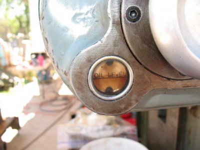
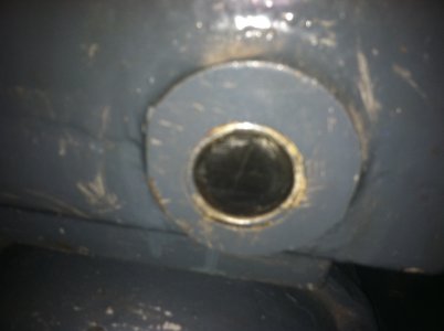
I was looking at the oil level windows on your VN 12 and I notice they are different from my machine that was built in 1944. My mill has what look like brass rings holding a piece of plastic (broken) in place. Were these window retaining rings threaded or pressed into position? I'd be able to tell except I bought the machine this morning and it's still on the factory floor where I purchased it. I'm hoping to bring it home next week. The guy is also selling a pair of Bridgeports one of which has a tracing attachment. I told him they were a bit above my price range.
 
truffeguy link=topic=1751.msg26523#msg26523 date=1316478854 said:
I was looking at the oil level windows on your VN 12 and I notice they are different from my machine that was built in 1944. My mill has what look like brass rings holding a piece of plastic (broken) in place. Were these window retaining rings threaded or pressed into position? ...
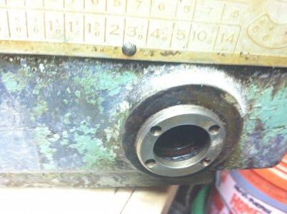
There were at least 3 different versions of the VN12 gearbox. The older ones, with the ball bearing gearbox like Josh's, used a threaded ring to hold the sight glass in place. Later versions used a pressed in assembly like this one:
 

Attachments

  • IMG_8918.jpg
    IMG_8918.jpg
    44.1 KB · Views: 38
Last edited by a moderator:
The gearbox from the 1943 Navy machine I parted out was better (in fact, a lot of things were better).

It has a larger, threaded insert for an oil sight glass:

023.JPG
 

Attachments

  • 024.JPG
    024.JPG
    1.8 MB · Views: 83
Last edited by a moderator:
Your 1943 sight glass looks more like the one on my machine. Mine is brass and was built in 1944.
 
The two geatboxes I have are entirely different. I think I like the 1943 Navy one better.

I am wondering if anyone ever replaced the sight glass, which is often broken, with a brass/glass sight gauge.

Nelson
 
The next picture shows the same view but with the drive shafts set in place (the bearing caps are still off). The middle segment (the part between the miter gears) nests inside the left and right hand tubes. Not shown in this picture is a third miter gear that connects the other two.
http://i841.photobucket.com/albums/zz339/weeble42/VN12/P1000993.jpg

The third pic shows everything reassembled with the bearing caps on. I'll try to describe how it works. The feed gearbox transmits power to a worm and wheel in the saddle. The wheel is visible on the right. The worm is fixed to the right hand segment of the drive shaft, and so this shaft turns too. A miter gear on the other end of this segment turns the center miter gear (the one at right angles), which then turns the miter gear on the left-hand segment of the drive shaft. So, the two outer segments of the drive shaft are turning, but in opposite directions. The center segment just floats between the two (the ends nest inside the other segments). The ends of the center segment are toothed, but you cannot see that because the teeth are hidden inside the left and right hand segments. All three segments are hollow, and the leadscrew passes through them.
Josh

I have the table off of my VN-12. And have removed the bearing caps. The drive train does not lift out. I suspect I have to remove that "third miter gear" in order to remove the drive train. There is a plug on the back of the saddle with two flat head screws. Is this the magic for getting the third miter gear loose? I don't have a stubby flat head screw driver (I don't like those things) or I would have already tried :))... tomorrow I'll get a stubby screwdriver.

Thanks,

Evan R.
 
Back
Top