Van Norman #12 Rebuild

weeble

Registered
Registered
Joined
Jan 6, 2011
Messages
20
Greetings!

In mid-January I bought a Van Norman #12 miller, and have slowly been cleaning it up. I came to this site seeking information and maybe a few parts. Nelson (allthumbz) asked me to write about my experience, so here I am.

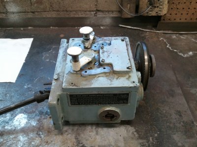
First of all, the mill was operational when I bought it. I was able to run it (the owner had native 3-phase) and make sure everything appeared to function correctly. The serial number dates it to 1942, although the war production tag is missing. I have one terrible cell phone picture of the machine as bought: P1000822.jpg P1000997.jpg P1000998.jpg P1000999.jpg P1010001.jpg P1000825.jpg P1000821.jpg P1000996.jpg
 

Attachments

  • VN12-1.jpg
    VN12-1.jpg
    52.1 KB · Views: 497
Last edited by a moderator:
The feed gearbox is also in pretty good condition. There is some corrosion on the shafts and a few patches on the gears, but nothing that will warrant replacement. I cleaned this one better than I did the ram gearbox (the corrosion had me worried at first). The bearings are open to the lubricant sump, and from the right angle you can see right into them. After getting all the crud out, I couldn't see any corrosion on the bearings nor could I feel anything by turning the shafts, so I decided not to pull the bearings.

FeedBox15.jpg FeedBox21.jpg FeedBox22.jpg FeedBox25.jpg FeedBox10.jpg FeedBox28.jpg FeedBox16.jpg
 

Attachments

  • FeedBox2.jpg
    FeedBox2.jpg
    239.5 KB · Views: 31
Last edited by a moderator:
The feed gearbox motor is not original. It is a 1980s era Dayton brand. Three phase, 1/4 hp.

The table is secured to the saddle with a tapered gib. The locking screw is on the left, the adjusting screw on the right. There are a couple of ways to remove the table: with or without the leadscrew. Using either method the table will come off to the left. Leaving the screw attached to the table is the easiest way. The right side of the table is attached to the screw with a bracket and a handwheel. Remove those, and then using the left handwheel traverse the table left until the leadscrew leaves it's nut. Then slide it the rest of the way by hand. It is very heavy; definitely a two-man lift or use a hoist. I seem to have neglected to take any pictures of just the table...probably because cleaning it up was so unremarkable. Other than the t-slots, there is really nowhere for crud to gather, and it cleaned up very quickly.

Removing the leadscrew from the table was more interesting. This may be a bit different for the various vintages of Model 12s; the thrust arrangement seems to have changed over the years. The left-side arrangement on mine is supposed to look like this:
P1000836.jpg VanNormanNo12BBp12-tablefeedmechanismleft.png
 

Attachments

  • RingSmall.jpg
    RingSmall.jpg
    203.7 KB · Views: 33
Last edited by a moderator:
Josh,

Looking good so far!

I added the photos - so that if you want to ever delete them from your photobucket we have them, and also, so I can print everything out as a guide for myself when I put my 1945 mill back together (I know, selfish motive).

You REALLY lucked out man- that mill was kept in darn good condition. You should see the 1942 when I first got it- looked like pure garbage. Covered in grease, paint peeling, had not been used in 10 or more years. Came off a Navy vessel, was sold to the guy I bought it from by Dave Ficken of Mermac, kept in his garage for 8 years, till he was forced to sell. What a mess. That is why I am using it as parts, though I think it actually saw less use. (Can't tell a book by its cover). The 1945 one was kept in OK condition.

The 3 HP motor is another bonus- mine are 1.5, a Diehl and a Westinghouse.

How are you going to set up a VFD with the 3 HP motor? Are you using 2 VFD's? I have a setup on here for that if you want to check it out:

http://hobby-machinist.com/index.php?topic=362.0

There are also some VN #12 wiring diagrams in the downloads section in here:

http://hobby-machinist.com/index.php?action=downloads;cat=29

Here are some photos of another restoration in which the owner used two VFDs in the control system:

newsightglass.jpg oldsightglass.jpg PB070063.jpg PB070066.jpg IMG_20101223_104236.jpg IMG_20101223_104309.jpg IMG_20101223_104451.jpg IMG_20101223_110732.jpg IMG_20110130_212032.jpg IMG_20110130_212119.jpg
 

Attachments

  • IMG_20110319_085834.jpg
    IMG_20110319_085834.jpg
    48.4 KB · Views: 407
Last edited by a moderator:
Thanks for putting the photos in line, Nelson! To be honest, I tried to do it that way first, but the size was timing out my slow connection. I'll have to continue using Photobucket for that very reason.

My original intent was to use VFDs. I already have a small one that can handle the feed motor; it seemed logical enough to get another for the workhead. However, the 3hp motor caught me by surprise. VFDs that will run a 3hp motor off of 220 single phase are pricy! I can get into a 5hp rotary phase converter for less money. I have a couple other three phase machines that I can run off of the same unit, so I'm leaning that way.

I'll agree with you that my mill was kept pretty clean - on the outside. The next set of photos will show some grime on the inside.

To remove the knee, the Y axis feed screw needs to be removed. It just bolts on to the front of the knee, and comes off easily. It would appear like you could remove the nut from the bottom of the saddle and leave the screw in the knee, but this is not the case. The nut is doweled to the saddle, and there is not enough play to remove the nut from the saddle without first removing the screw. Once the screw is out, the saddle will slide off the front of the knee (you may need to loosen the gib first). The telescoping shaft that connects the feed gearbox to the saddle just slides apart, so no worries there if you haven't already removed the gearbox.

The first picture shows the saddle looking down from the top, exposing the table drive mechanism:
http://i841.photobucket.com/albums/zz339/weeble42/VN12/P1000988.jpg

Next shows the saddle standing on edge to show the underneath. The gib is still attached, as is the worm gear (not visible under the blue keeper plate at the top of the picture):
http://i841.photobucket.com/albums/zz339/weeble42/VN12/P1000986.jpg

There was enough gunk in here that I decided to break it down and clean it up good. The following photos are post clean-up, with the saddle back on the knee. The first shows the bare casting with all the drive parts removed. Notice the lubrication channels in the bearing blocks. These come from oil ports in the back of the saddle (the side closest to the column).
http://i841.photobucket.com/albums/zz339/weeble42/VN12/P1000990.jpg

to be continued...
 
The next picture shows the same view but with the drive shafts set in place (the bearing caps are still off). The middle segment (the part between the miter gears) nests inside the left and right hand tubes. Not shown in this picture is a third miter gear that connects the other two.
http://i841.photobucket.com/albums/zz339/weeble42/VN12/P1000993.jpg

The third pic shows everything reassembled with the bearing caps on. I'll try to describe how it works. The feed gearbox transmits power to a worm and wheel in the saddle. The wheel is visible on the right. The worm is fixed to the right hand segment of the drive shaft, and so this shaft turns too. A miter gear on the other end of this segment turns the center miter gear (the one at right angles), which then turns the miter gear on the left-hand segment of the drive shaft. So, the two outer segments of the drive shaft are turning, but in opposite directions. The center segment just floats between the two (the ends nest inside the other segments). The ends of the center segment are toothed, but you cannot see that because the teeth are hidden inside the left and right hand segments. All three segments are hollow, and the leadscrew passes through them.

The leadscrew has a keyway cut it it, like the leadscrew on South Bend lathes. A key is attached to the center segment of the table drive. When the center segment is slid to either side of center, say, to the right, then the teeth on the center segment engage teeth on the inside of the right segment. The center segment is now being turned by the right-hand segment, and the leadscrew (driven by the sliding key) turns. The same thing happens when the center segment is shifted to the left, but the screw moves the other way. It is worth noting that the drive shafts are always moving, even if the table is not.
http://i841.photobucket.com/albums/zz339/weeble42/VN12/P1000994.jpg

The last picture shows the underneath when mounted on the knee. You can see the socket where the Y-axis screw goes, and the pad where the nut will mount. The nut bracket curls around into the screw socket. Also you can see the keeper plate that holds the worm in place. This has an adjustment mechanism to control the engagement of the worm and wheel built into it.
http://i841.photobucket.com/albums/zz339/weeble42/VN12/P1000995.jpg

I'll continue with the knee and column tomorrow.
Josh
 
The knee is perhaps the easiest of the big parts to remove. Raise it up until the screw runs out of the nut, then unbolt the gib and lift it off. It was also easy to clean...no place for crud to accumulate, really. I did not remove the screw or handwheel assembly, just cleaned it from the outside. Here is a picture showing the knee, table, and saddle prior to cleaning:
 
weeble link=topic=1751.msg11037#msg11037 date=1303177992 said:
Thanks for putting the photos in line, Nelson! To be honest, I tried to do it that way first, but the size was timing out my slow connection. I'll have to continue using Photobucket for that very reason.

Apologies for putting the photos in- I didn't think about load times. I will leave them be from now on.

Thanks,

Nelson
 
Last edited by a moderator:
weeble link=topic=1751.msg11171#msg11171 date=1303247307 said:
Underneath all that crud was an old repair: one corner of the base around one of the leveling screws had been broken off and brazed back together. I tried to photograph it, but it doesn't show up well. The piece that broke off is about 10" by 4". The only way I can think this may have happened is for the machine to have been dropped. However, the break is in a completly non-critical place, and the repair is solid. I can't see how it will effect the performance of the machine, so I have decided to not worry about it.

Dang! Too bad you don't live closer- I will GIVE you my 1942 base. I cleaned, degreased, bleached the inside and repainted it rustoleum smoke great and it looks great. I want someone with a broken base to use it.

Nelson
 
Last edited by a moderator:
Reassembly was much easier than I expected. Starting with the bare column, I mounted the feed gearbox first:
http://i841.photobucket.com/albums/zz339/weeble42/VN12/P1000971.jpg
http://i841.photobucket.com/albums/zz339/weeble42/VN12/P1000972.jpg

Then I went around to the front side of the column and mounted the knee:
http://i841.photobucket.com/albums/zz339/weeble42/VN12/P1000973.jpg
http://i841.photobucket.com/albums/zz339/weeble42/VN12/P1000977.jpg
http://i841.photobucket.com/albums/zz339/weeble42/VN12/P1000981.jpg

Next the bare saddle went back on the knee, and then the table drive components were replaced in the saddle.
http://i841.photobucket.com/albums/zz339/weeble42/VN12/P1000994.jpg

The table was next. Rather than use a lift, I borrowed my burly neighbor. I was easy with two people.
http://i841.photobucket.com/albums/zz339/weeble42/VN12/P1010012.jpg

And then on to the ram. My neighbor and I also lifted the ram in place, and probably shouldn't have! It's just a little to heavy and cumbersome. Although we did it, I won't do it again!
http://i841.photobucket.com/albums/zz339/weeble42/VN12/P1010002.jpg
http://i841.photobucket.com/albums/zz339/weeble42/VN12/P1010003.jpg
http://i841.photobucket.com/albums/zz339/weeble42/VN12/P1010004.jpg

The motor mount and belt tension adjustment plates went on next, followed by the motor.
http://i841.photobucket.com/albums/zz339/weeble42/VN12/P1010005.jpg
http://i841.photobucket.com/albums/zz339/weeble42/VN12/P1010006.jpg
http://i841.photobucket.com/albums/zz339/weeble42/VN12/P1010007.jpg
http://i841.photobucket.com/albums/zz339/weeble42/VN12/P1010008.jpg

At this point, the major assemblies are together. Some pictures of the whole mill:
http://i841.photobucket.com/albums/zz339/weeble42/VN12/P1010011.jpg
http://i841.photobucket.com/albums/zz339/weeble42/VN12/P1010013.jpg
http://i841.photobucket.com/albums/zz339/weeble42/VN12/P1010014.jpg

Although "together," ,the mill is not yet ready to run. I still have to put up many small parts (covers, pulleys, guards, etc.), lubricate, and adjust the machine. I also have to repair or replace a handfull of small parts.

Additionally, I did not show any pictures of the work head. When I bought the machine the spindle had an arbor stuck in it that simply would not come out. Eventually it came out, but I had to completely disassemble the work head to do it. That's when I discovered the spindle had be re-bored to B&S #9 taper. I want to return to the original VN C, and so I'm seeking a replacement. When I find one, I'll finish the thread with pictures.

Thanks for reading,
Josh
 
Back
Top