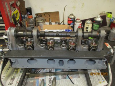
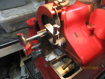
I titled the thread valve train geometry, so I'm going to show how it's done; first pic, the head mounted in the work fixture with the cam installed, the steel strip mounted on the gasket rail is for mounting the mag base for the dial indicator.
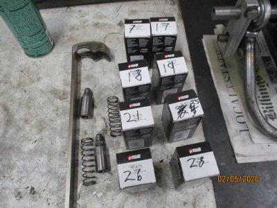
The first thing I do is transfer the number on the cam follower to the outside of the box, the followers will be installed with the smallest number on #1 exhaust, the next on #1 intake, and so on. This helps me keep track as I will do the exhaust side first.
The valves are in the head at 8 degrees from vertical and the indicator must match that or it will induce cosine error, I use a square, angle blocks, and a surface plate to set up the indicator.
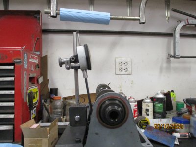
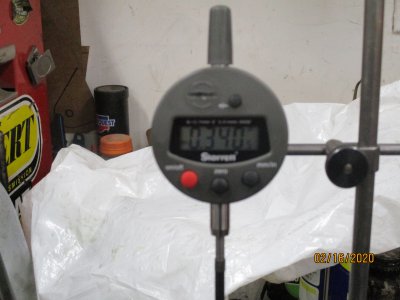
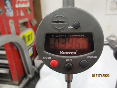
OK, now I get to show off my new toy, my son got me this on some online auction. It's metric and standard and has a +- function so I can pre-load the indicator, cycle the cam, and directly read the lift.
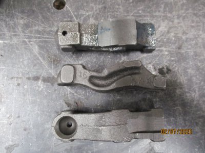
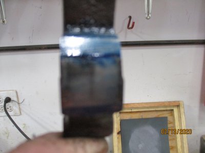
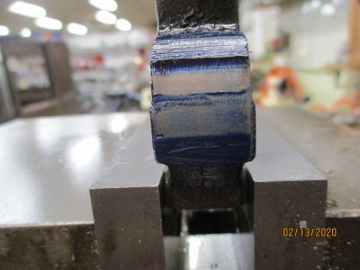
Now comes the fun part, shorten the stem until you get the advertised lift. The first measurement is .340. I know that the new valves are +.100 of stock stem length, since I'm using a stock cam and rockers the finished length will be somewhere near stock length, I will remove .070", this gives me a lift of .386" and removing another .015 gives me the final lift of .396", as long as I am within .005" of the target it's good. Repeat this process 7 more times and you're done. the first follower shows the contact patch at .340" lift, and the second is the patch at .396", you can see how it is better centered than the other.
All I have to do now is install the hydraulic adjusters and make sure I have .050" minimum clearance when fully collapsed, and then install the head of course, Happy Motoring.