- Joined
- Dec 18, 2019
- Messages
- 6,464
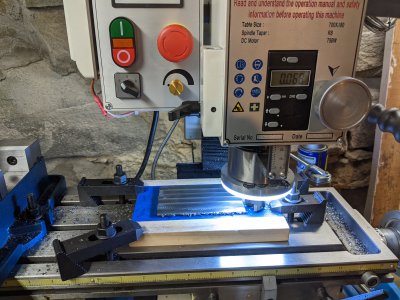
I have a little project to copy a bed bracket. The part I need to duplicate is only 1/8" thick flat and has a slot milled in it so it can engage in a receptacle. I have the piece, but not the receptacle. So I got a piece of wood and covered it in painter's tape and then super glued the back of the workpiece to the painter's tape. I clamped the piece to the table of my mill.

I was able to fly cut the part to the correct thickness and mill the part to size. Unfortunately, the tape adhesive failed at the wood interface and the part started to move. The super glue did not fail. Fortunately, the piece is still ok. So I peeled everything off and need to start again. One of the issues is the clamps are very large compared to the available dimensions of the mill stick out. It was difficult to set up without interference with the spindle (or spindle light) and the studs of the hold downs.
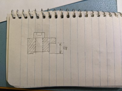
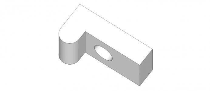
For the redo, I was thinking of using a smaller piece of 6061 3/8" thick with different hold downs for the sacrificial plate. For the hold downs, envisioning something simple like an inverted "L". But I'm not sure how to make the L cam downward and hold down the 3/8" thick plate. Would something like this be ok, or what do you suggest?

It seems there are all sorts of commercial items, but the choices are difficult to wade through. Most assume you know how they work, how to use them and how adjustable they are. As a beginner, I don't know any of that. A lot of the clamps are quite expensive, so I thought I might make something simpler. I realize the design above is non-adjustable, at the moment, I just want to finish what I had started. I'm looking for a simple lower profile hold down. If it matters, my tee slots are 12mm with 3/8-16 threads.
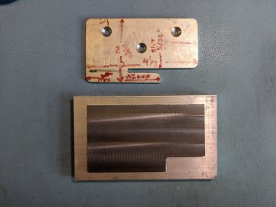
Here's a picture of what I'm trying to copy and how far I got before the tape let go. The aluminum is what I want to use for the new sacrificial plate. Wish it was larger, but I'm finding it hard to justify cutting up my limited stock just for this. The dimensions on the plate are very rough but give an idea. I found that none of them were accurate to fabricate from. (I didn't mark up the plate.) The counter bores are not required in the application, but the holes are. Basically, all I have to do is a slot and the 3 holes plus clean up. I'd stick it in a vise, but don't think it is wise to mill the slot that way. Is there a simpler (better) way to do this without making the hold downs? Although in the picture these pieces look to be of different size, they are the same. Thanks for any and all help.


I was able to fly cut the part to the correct thickness and mill the part to size. Unfortunately, the tape adhesive failed at the wood interface and the part started to move. The super glue did not fail. Fortunately, the piece is still ok. So I peeled everything off and need to start again. One of the issues is the clamps are very large compared to the available dimensions of the mill stick out. It was difficult to set up without interference with the spindle (or spindle light) and the studs of the hold downs.
For the redo, I was thinking of using a smaller piece of 6061 3/8" thick with different hold downs for the sacrificial plate. For the hold downs, envisioning something simple like an inverted "L". But I'm not sure how to make the L cam downward and hold down the 3/8" thick plate. Would something like this be ok, or what do you suggest?

It seems there are all sorts of commercial items, but the choices are difficult to wade through. Most assume you know how they work, how to use them and how adjustable they are. As a beginner, I don't know any of that. A lot of the clamps are quite expensive, so I thought I might make something simpler. I realize the design above is non-adjustable, at the moment, I just want to finish what I had started. I'm looking for a simple lower profile hold down. If it matters, my tee slots are 12mm with 3/8-16 threads.
Here's a picture of what I'm trying to copy and how far I got before the tape let go. The aluminum is what I want to use for the new sacrificial plate. Wish it was larger, but I'm finding it hard to justify cutting up my limited stock just for this. The dimensions on the plate are very rough but give an idea. I found that none of them were accurate to fabricate from. (I didn't mark up the plate.) The counter bores are not required in the application, but the holes are. Basically, all I have to do is a slot and the 3 holes plus clean up. I'd stick it in a vise, but don't think it is wise to mill the slot that way. Is there a simpler (better) way to do this without making the hold downs? Although in the picture these pieces look to be of different size, they are the same. Thanks for any and all help.


