Spindle bearing woes

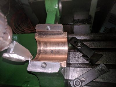
So today I got a chance to get my car back together, clean off the mill table, tram the head (good thing I did it was out .01) and took a cut on the head stock.
The left side bearings are now showing an even +10 all around the right front is +13 all around and the right rear didn't get cut But, we knew that going in.
I've got all that stuff. I used to work at a plastic injection mold shop so I've got a decent amount of 0-12" measuring tools a set of gauge blocks a matched pair of V-blocks. Anything else I might need I don't mind adding to my collection! :)
So what's the next step?IMG_20181007_222522.jpg
 
Hi Izzy,

The left side bearings are now showing an even +10 all around the right front is +13 all around and the right rear didn't get cut But, we knew that going in.

We now need to find out how much we have left !
Don't put the spindle back in. Place the caps on the headstock and see what the gap is between the bearing shells if any. Both at the chuck end and at the tail end. Measure with a feeler gauge at both ends of the bearing shells.

I'm working towards reducing any gap to zero and looking to have a gap between the top of the pillar and the cap, however small.
 
Assemble the caps and check the bore now? Torque caps to get a consistent reading. See if you’ve changed the taper.
I’d get some dykem or canode to blue your surface to check contact.
 
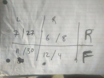
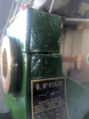
I put the caps back on and the bearing halves are now contacting and there's a gap between the "pillars" and the caps albeit not even what so ever but, there is a gap there. The Gap is tapered enough that it can be seen by eye though. I didn't torque the caps down in fear of cracking them with the Gap that was there. Here's what I measured with feeler gauges and caps not torqued down. I can re-measure with the caps torqued down if necessary just didn't want to risk it without asking first. I don't want to screw anything up.

15390236824864992499745353613353.jpg

IMG_20181008_135455.jpg
 
Hi Izzy,

Thats good ! I'm glad that you didn't risk cracking the caps, it would have been game over.
The measurements with the feeler gauge, is that the gap between the bearing shells along the line of the joint.
 
I would not torque them down yet. I would think you need to now correct the caps straight surface. Trying to shim a taper on 4 corners that arnt equal is gonna be a nightmare.
I’m thinking of this as connecting rods and crankshaft main caps which I’m very familiar with. Those caps need a flat and parallel surface to mate too. With the cap being taper you will never get even load on the bearing causing premature familiar.
As for how to get those surfaces parallel with the bottom. I would try putting the assembly on a flatest surface you have. While having caps on I would use a height gauge and go around the assembly finding the highest point on caps. Then scribe the others to match that height. Then align on mill and level them out.
Then you will be able to use know shimstock and make up the difference not worrying about front to rear being off. Just a idea.
 
I would not torque them down yet. I would think you need to now correct the caps straight surface. Trying to shim a taper on 4 corners that aren't equal is gonna be a nightmare.

I agree, its going to be an issue to be sorted, when we get to it !

As for how to get those surfaces parallel with the bottom. I would try putting the assembly on a flatest surface you have. While having caps on I would use a height gauge and go around the assembly finding the highest point on caps. Then scribe the others to match that height. Then align on mill and level them out.

The problem with doing that is we don't know how the shells have worn ! At some time in its life the caps have been assembled using those surfaces, we need to find out if the shell wear is even or canted crooked. All we have at the moment is some surfaces that we know are flat.

Then you will be able to use known shimstock and make up the difference not worrying about front to rear being off. Just a idea.

Down the line the use of shims will probably be required, and parallel surfaces would be an advantage.
 
The gap was measured between the bearing cap and the "pillars" of the head stock as you called them before. The bronze bushings themselves dont have a gap anymore they are touching.
@Cadillac I'm a licensed mechanic and almost went through for my general machinist license as well and i view the spindle vary similaryily like you do, just like a crank shaft. Both have caps and journal bearings and require extreme accuracy for a long life. Either way I'm ready and eagerly awaiting the next steps! :)
 
Hi Izzy,

Good, I just needed to confirm that the bearing shells were meeting without any gap, and that the gap was between the top of the pillar and the cap.

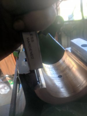
Use calipers to measure down the inside of the bearings at 90 degrees to the shell joint faces. Whilst the actual diameter isn't important at the moment how parallel the bearing is, is. If you can get an accurate diameter then all well and good.

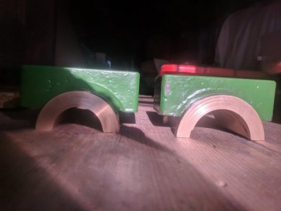
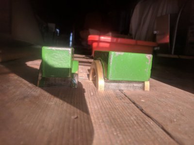
As Cadilac mentioned we are going to have to sort out the taper on the faces of those caps. Can you post a couple of pictures of them, top, front and sides please.
 
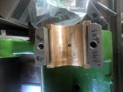
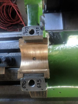
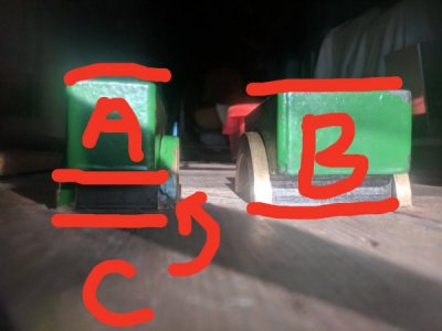
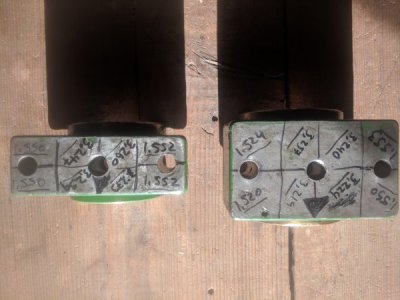
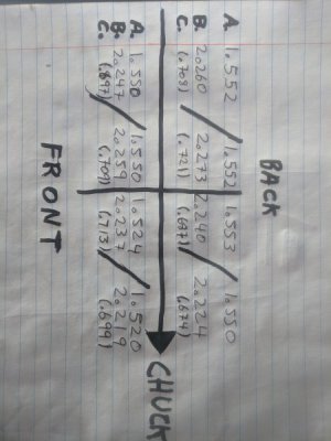
Alright so I took a bunch of measurements today and I got the pictures you wanted. Just to verify the first picture is the measurement you where looking for? If so the next pictures have all my measurements I also measured the bearing caps with a mic out of curiosity. I think we can gather from this that it's the step in the caps that are tapered. Let me know what you think and what my next step is.IMG_20181009_155743.jpgIMG_20181009_162550.jpgIMG_20181009_162558.jpgIMG_20181009_165414.jpgIMG_20181009_165443.jpgUSER_SCOPED_TEMP_DATA_orca-image-120291050.jpeg_1539120732128.jpegIMG_20181009_165509.jpgIMG_20181009_181736.jpg
 
Back
Top