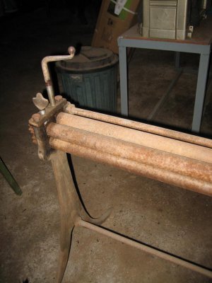
Slip Roller

Ray C

Registered
Registered
Joined
Nov 16, 2012
Messages
5,596
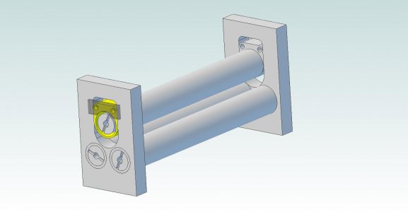
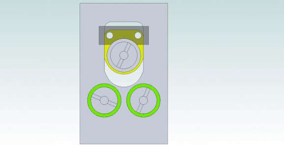
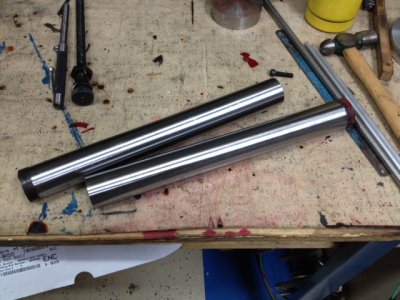
I've got a couple projects coming up that will need a slip roller and will need to make one in the next two weeks. Here's a quick CAD view of the approximate design. I might tweak this a little bit more but this is what it's looking like so far. This will be made out of 1045 and everything will be hardened. The rollers were cut today and are currently 1.410" diameter and will be hardened to somewhere around RC 48-50 then brought down to 1.400" (and I'll use the dreaded ceramic inserts for the final cut). They're 12" long and the pinch area is 10.5" long.

In the drawings, the green circles are needle roller bearings (I forgot to insert a bearing on the top roller). There will be a tapped hole and bolt at each end (not shown yet) to compress the yellow roller guides downward. I ordered some 1x1.25x3/4 needle bearings that have a 40,000lb static rating -way more than enough to make the stainless steel hoops I need to make. The shaded plate with a semi-circle is a keeper tab to hold the top roller and can be taken off to remove the roller when forming full loops.
SlipRoller.jpgSlipRollerProfile.jpg

RollerBar1.jpgRollerBar2.jpg

I'll show pics as this progresses...


Ray

SlipRoller.jpg SlipRollerProfile.jpg RollerBar1.jpg RollerBar2.jpg
 
Love to see it in action when you are done. I am also very interested in the finished obtained with the ceramic. I've never thought about using ceramic bits.
 
Ray,
How do you intend to drive it?
And if this is for your own use, a couple of extras to consider.
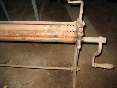
On my roller, the top pinch roller is located above, and in line with the roller below it. This is adjustable for varying thicknesses.
The 3rd roller is also adjustable, but to a much greater degree for making gentle to tight radius curves.
To keep rods and such located on the rollers, 1 pinch roller has a couple of grooves machined in it, and also the outfeed (3rd) roller has matching grooves as well. This stops the rod from tracking along the rollers when you make hoops.
Mine also has the 3rd roller adjustable in different amounts from 1 end to the other. That lets you roll a "compound" curve in a sheet. They come out cone shaped.

Cheers Phil

Now darn it Phil, you got me thinking on another track now -and I need this thing in a couple weeks. Have you seen the prices on these things? -Talk about profit margin!

Anyhow, I've never used/seen a slip roller before so I looked at a few pictures and saw the design you're talking about. I was planning to put at least one wire-guide groove in there.

In my observations, the ones designed like yours tend to be motorized or have a large radius cranking handle. The one I'm making needs to be small enough for benchtop use. I'm planning to clamp it in a vise when in-use. It makes me wonder how much muscle power is needed to manually crank one of these things. I have two jobs coming up that need bends. One is stainless steel (about 1/16" thick material) 4.5" diameter and 10" wide/tall (think custom made oil filter container). Another has steel strips 1/8" thick, 1/2" wide with a gradual 90 degree bend of about 3" radius.

So... not knowing how hard it is to crank the handle, I came-up the fixed two bottom rollers because I stand a chance of driving both simultaneously with a gear (or gears) -in hopes that two drive rollers helps overcome any difficulties cranking the pieces through.

There's the current strategy and as usual, any info about the realities of using one of these things would be helpful.


Ray
 
Here's a little eye candy...

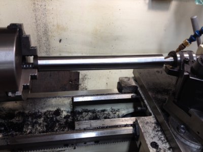
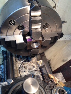
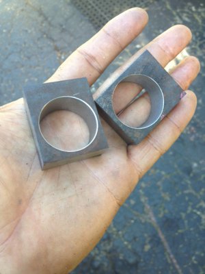
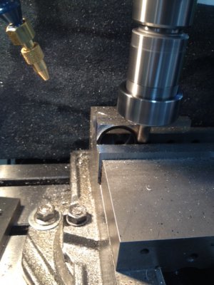
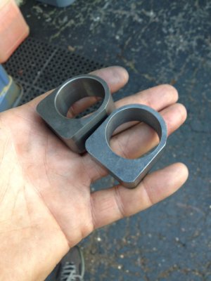
Here are the bearing holders... See guys, I didn't forget how to use the old lathe despite all the CNC lately. (Actually, most of my custom work is manually machined). This needed a little of both. I setup and bored the offset hole in the 4 jaw and made the corners and bottom radius on the CNC.

The bearings are 1.250" OD. The bores came out to 1.2495 and 1.2496" as best I can measure them... They'll be a slight sweat fit.

Here you go...

BG1.jpgBG2.JPGBG3.JPGBG4.JPG

Ray

BG1.jpg BG2.JPG BG3.JPG BG4.JPG
 
Looks good but ya got the holes off center. Ya should have programmed it. :lmao:
 
Are you going to make one end open up, or are you going to pull the top roll to take your parts off? That's if you're going to be rolling complete circles.
 
Are you going to make one end open up, or are you going to pull the top roll to take your parts off? That's if you're going to be rolling complete circles.

I'll need to take the tab off one of the bearing holders and slide the top roll out. I didn't feel like dealing with all the complication of a more sophisticated design (although I was thinking about it)...


Ray

- - - Updated - - -

Are you going to make one end open up, or are you going to pull the top roll to take your parts off? That's if you're going to be rolling complete circles.

Yeah, they're a tiny bit off to one side but all is well and I got lucky for two reasons... Both are off the same amount. Both are a little over-sized and when I mill them to correct size, I'll take a little more off on one side... (wheew... dodged a bullet on that one). Fortunately, it doesn't matter anyhow because the height of top shaft is controlled with two independent adjustment bolts... I think Father's Day luck was on my side today...


Ray
 
A nice project you got there.
Had some experience running a 3' wide, motor driven one some years back.
It was adjustable in ways I hadn't known existed and all three rollers were geared to each other for maximum drive power.
I saw a home made unit just 6" wide that had only two rollers driven. It slipped more than it rolled.
The list of things I want to build just got longer.
 
I think you should go back and get them both the same........
The bores came out to 1.2495 and 1.2496" as best I can measure them...


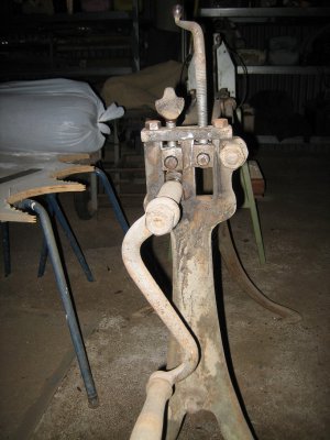
The crank handle on mine is 10" long IMG_6277_zpsabdb2a63.jpg IMG_6276_zpsf75b8ca9.jpg


You can see how much adjustment I have on my outfeed roller. IMG_6279_zps973905b0.jpg

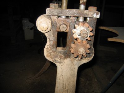
And because the rollers are just in sloppy bushes you can crank 1 end more than the other to give you the "compound" curve IMG_6278_zpse164a561.jpg

I wouldnt even raise a sweat on your job, pretty sure I could wind a 3" radius on mine, but that would be about as tight as it would go I reckon.
Its not that strenuous to do. If you try to push it too hard it just gets too difficult to crank the handle. Just go back and forth adding a bit more pressure each time to tighten the curve.

Cheers Phil

IMG_6277_zpsabdb2a63.jpg IMG_6276_zpsf75b8ca9.jpg IMG_6279_zps973905b0.jpg IMG_6278_zpse164a561.jpg
 
Back
Top