Slant-Bed CNC Lathe Build

I take it the Galil can be wired so one limit switch performs both Home and Limit duties? That seems like a really slick way to get the job done on a few machines I've seen.

Honeywell's BZE6 series switch seems like a good fit here, and there's lots of them available online for reasonable prices (~15$)
https://sensing.honeywell.com/honey...v6-limit-switch-product-sheet-002383-2-en.pdf

Do the contact rollers introduce meaningful tolerance vs. a solid-stud plunger switch? Roller has moving parts, but the solid hard stud would be affected by faster wear (either it or the contact surface)
 
You'll need an encoder - US digital has them for about $75 each. Or go real top end with linear strips. many servo offers include the encoder.

I don't suppose you have any recommendations for linear encoders? The AMS AS5311 seems to have some DIY usage (CNC Zone's been down all day so it's hard to answer the question) but I really need a primer on how these are set up, since they don't seem to be a turn-key product, but a component (the linear strip, AS5311 sensor, the board that it mounts to, and the interface with the controller are all separate)
 
Yeah, I'm thinking that, too (would also be nice even on Z as a safety mechanism though).

Not to drift my own thread too terribly much, but I am considering a much more upright slant configuration (60deg vs 45) and the brake really would become a necessity. My discussion about ganged-tooling earlier got me thinking; gangs don't work very well if you have a tailstock supported workpiece (unless I'm missing something) and my 7" max stickout would stand to benefit from that ability. So how to get the tool gang around the workpiece so the desired tool can be selected?

If the headstock itself can move about 2-3" at an angle to the X-axis (across the table toward the operator in this case) the tool gang could slide freely behind the work piece without interference. This would not be a controlled axis but a momentary shift similar to a powered draw-bar. Combine that with a similarly 'dumb' tailstock center which can engage or disengage from the end of the workpiece a short distance. It seems like it'd be a pretty fast way to change tools without adding a ton of complexity or volume (maybe some loss of rigidity?) I'd be able to put right and left hand side tools at opposite corners of the gang positions and cut on the full 24" interior length between the spindle and the far wall. Anyone try something like this before?

The only slant bed lathes with a tailstock that I have seen have a turret rather than gang tooling. I could imagine a system that would retract the tailstock, change the gang position, then move the tailstock back into position or something like that.
 
I take it the Galil can be wired so one limit switch performs both Home and Limit duties? That seems like a really slick way to get the job done on a few machines I've seen.

Honeywell's BZE6 series switch seems like a good fit here, and there's lots of them available online for reasonable prices (~15$)
https://sensing.honeywell.com/honey...v6-limit-switch-product-sheet-002383-2-en.pdf

Do the contact rollers introduce meaningful tolerance vs. a solid-stud plunger switch? Roller has moving parts, but the solid hard stud would be affected by faster wear (either it or the contact surface)

Don't worry about tolerance, the limit switch is just to get you close. The final home position is set with the Z pulse from the encoder. I like the roller switches and a cam to actuate.

I don't suppose you have any recommendations for linear encoders? The AMS AS5311 seems to have some DIY usage (CNC Zone's been down all day so it's hard to answer the question) but I really need a primer on how these are set up, since they don't seem to be a turn-key product, but a component (the linear strip, AS5311 sensor, the board that it mounts to, and the interface with the controller are all separate)

You are planning on building your own linear encoder read heads? That would be an ambitious project. :) I use Ditron linear encoders, they wire right into the Galil. Have a look at this thread where I installed a DRO on my manual lathe. https://www.hobby-machinist.com/threads/lathe-dro.58063/
 
Last edited:
I take it the Galil can be wired so one limit switch performs both Home and Limit duties? That seems like a really slick way to get the job done on a few machines I've seen.

It is possible to do that with the latest generation cards by using the LD command. There is also a workaround in software for the older cards using the CN command.
 
Don't worry about tolerance, the limit switch is just to get you close. The final home position is set with the Z pulse from the encoder. I like the roller switches and a cam to actuate.


You are planning on building your own linear encoder read heads? That would be an ambitious project. :) I use Ditron linear encoders, they wire right into the Galil. Have a look at this thread where I installed a DRO on my manual lathe. https://www.hobby-machinist.com/threads/lathe-dro.58063/
Ah, right; the index pulse; of course!

I wasn't hoping to have to build one, I just can't access any CNC Zone threads where people implemented that sort of linear encoder ;). Most stuff I find is glass-scales which are usually a 'sealed unit' from what I understand (generally sold as a drop-in kit)

Also, after looking into the Ditron & Renishaw encoders, it really doesn't look like magnetic is any cheaper than glass (>100$/axis); just more easily trimmed to fit & a good bit smaller. Also doesn't appear to be nearly as common. I do notice there's a ton more Chinese glass scales for sale than I remember seeing, so I guess the Politburo has decided to target that industry for the moment & it's driving prices down. I'll put scales on the back burner for the time being and focus on firming up the physical layout now that the bulk of the electrical architecture is decided.
 
If you know of Ditron still selling the reader & tape for ~150$ I'd love to know; the only 1um magnetic reader I can find from China is 250$/per and the tape 100$/m (about what I'd need). Comparable accuracy glass scale assembliess are about 100$ per axis.
 
The glass not sealed tight, they do get dirty after a time.

Contact Jaeger at Ditron for a quote.
sales@dcoee.com

Feel free to say I recommended him.
 
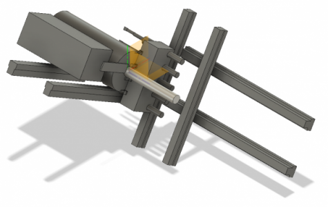
Here's a concept of the idea I mentioned earlier, about adding a true third axis to the lathe by moving the head stock.
3 Axis Concept ISO.png

If a 2-axis is a 'slant bed,' this would be a 'V bed.' Here are the high points;
1) I'm designing from the cut area outward, hence the floating parts
2) X axis is kicked up 60degrees, with about 3.5" of travel up and down from the position shown (it's the steep axis on the right in this view)
3) Y axis is therefore 30degrees above horizontal, the spindle & motor will move along this. Motion is about 1.5" up/out, 4" down/in (more later)
3a) Servo motor points down & hangs between the axis rails
4) Z axis is a normal left/right orientation, with 12" of travel to the right from the position shown (more later)
4a) Servo motor at the same elevation as the upper/back Z rail, behind the spindle
Tool Plate Concept.png

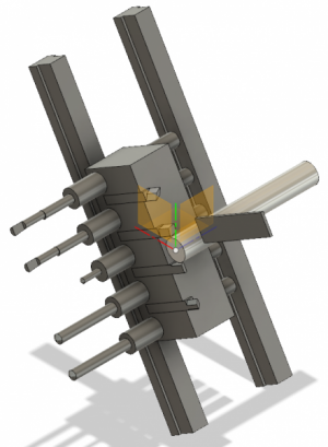
Tool plate layout (opposite angle to the first view, spindle/motor/Y&Z axes hidden). Like I said, I've been around Swiss lathes a lot lately, so the thing I have here is almost a hybrid of a gang-plate and a dog-leg;
1) Turning tools sit atop a post clamped into the tool plate. Rather than the cut load trying to 'bend' the tool, it is trying to 'compress' the shank
1a) Tool shanks secured in a slot by a wedge-clamp (probably a standard Swiss format clamp)
1b) The 'post' presenting the tool will have a cutting edge on its top & bottom side, so a left-hand tool can be used if the spindle is reversed
1c) If possible, a symmetric insert laid orthogonal to the XZ plane will accomplish 1b, cutting on both exposed edges
1d) The tools are selected by raising the headstock, sliding the tool plate to another 'gap' between cutters, and dropping the workpiece back down
2) Drilling and boring tools are located below the stack of turning tools, held in ER16 collet holders bolted into the tool plate
2a) These tools are accessed by sliding the toolplate about 4" along Z, then dropping the headstock down near its limit of travel
2b) To make room for these tools' stick-out, the Y axis rails move with the headstock (the carriages are fixed)
2c) These tools are 3" below the C/L of the turning tools, so with proper caution objects as large as the spindle OD can be swung if needed
3) The headstock moves up .6" to clear the turning tools; as it moves another .6" upward it hits a frame-mounted parting blade near the collet
4) The four tool spots up top are; L/R 55deg roughing insert, L/R 36deg finishing insert, HSS round/square grooving, HSS L/R 60deg thread
5) The five ER16 parts are; spot drill, two twist drills, ID boring tool, ID threading tool

Things I like about the idea so far;
1) Drills can be as long as the spindle if needed (or bore 6" deep in a 6" part)
2) Very high density of tooling; I have 14 cutting edges shown, all available at all times (for 99% of operations I'm likely to need)
3) Possibility of small live air-tools in the ER16 holder spots (some day)
4) Possibility of a live air-tool in the 3/8" bar slots (though it would block a number of other tool positions)
5) Mirrored turning tools could be mounted at the right-side of the tool plate, for turning a larger area than allowed by the Z travel alone
6) Tool changes seem like they would be very fast; as fast as rapiding to any particular point on a mill
7) The X and Y support beams will form an X truss in the frame
8) Possbility of a tailstock since the workpiece goes right over the top of the toolplate
9) It's really easy to blank off the Y-axis stuff & have my 2-axis layout if I decide not to go 3-axis ;)

Things I don't like;
1) Very careful programming & sequencing would be needed for everything, since crash-points are everywhere (just like a Swiss)
2) Would need to grind custom insert holders & HSS tools for the turning positions since the orientation is unusual (roller-box tool bits are similar)
2a) I honestly don't know if that sort of tool/workpiece arrangement even works w/o rollers; usually tools are loaded on the side, not the end
3) The spindle is cantilevered off its supports when it drops down to align with the drilling tools (about 3 inches)
4) The headstock gets a little complicated compared to bolting a spindle cartridge to a thick plate on the frame
5) Moving headstock likely makes powered collet actuation more difficult
6) One more degree of backlash on a light weight machine to worry about (but mills get by, so maybe not a big issue in practice)
7) Wild guess that the moving head-stock end will make coolant & chip-guarding more difficult
8) No good spots to put the X-axis servo motor; an 8:1 in-line planetary might be the best route for this one axis
9) As modeled, it's about a foot from the door to the Y axis rails to the spindle C/L; this seems awkwardly deep for access
9a) Tool setting looks at least as tight & awkward as for Swiss lathes
 
Last edited:
You're making my head hurt. :faint: But a very interesting concept. :)
 
Back
Top