Showing off my RC model boats

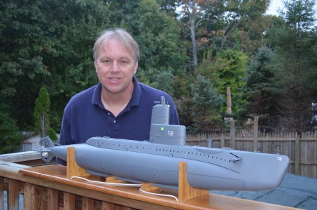
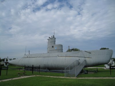
The next model I will cover is a submarine, the USS Marlin. You can look up the Marlin on Wikipedia. This is a styrene kit that was designed and sold by a friend of mine, Skip. Skip was a member of our model boat club which formed around 77. He got into model subs and started his own business, not sure when that was. I got this kit from him around 2000 and didn't start building it around 2011. The full build is on RCGroups. I will cover it here in very very condensed form. The real boat is a museum in Omaha, not sure how good shape it is in. The model was designed to try and catch peoples interest in model submarines. It was not made to have the detail that is there on the real sub, but I went way beyond this and detailed it out the wazoo as you will see.

I'll explain later how you get a model submarine to dive and surface.

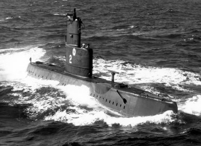
Pics of the real Marlin.

AA 600IMG_3058.JPGAA marlin1.jpg

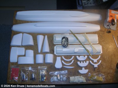
Contents of the entire kit to begin with.

A MAR0010-PB130232.JPG

And the building begins.

B MAR0025-PB190260.JPG

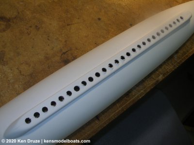
Holes need to be drilled in to bottom to let water in to the interior. Likewise, holes also need to be on the deck to let air out.

C MAR0038-PB200263.JPGD MAR0044-PB210280.JPG

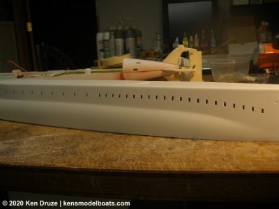
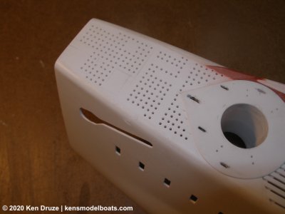
These holes in the side had to be drilled and filed. They are functional for the model and can be seen on the real boat.

F MAR0061-PB220320.JPG

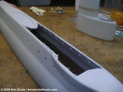
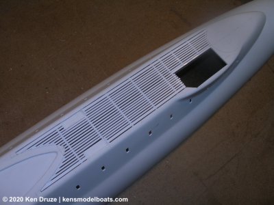
The decks forward and aft of the sail (or conning tower) had to be opened up so realistic decking could be installed.

G MAR0076-P3240363.JPG

Here that more realistic decking can be seen. This is the aft section.

H MAR0087-P4120410.JPG

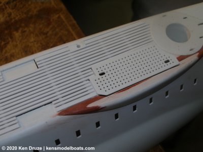
This is the forward deck area.

I MAR0106-P5050370.JPG

This is the more forward area on the forward deck up near the bow. All of these holes were drilled on the drill press.

J MAR0110-P5060345.JPG

Making progress.

K DSC_0160.JPG

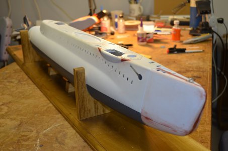
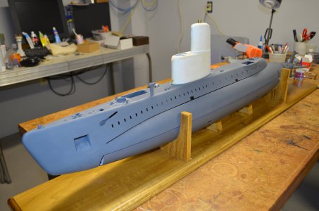
At this point deck hardware, cleats, bits, more had been added. All hull opening have been done and the hull painted. Work on the sail is in progress, more in the next post. And I made a stand.

L D_DSC_0102.JPG
 
Here I will explain in detail about the sail.

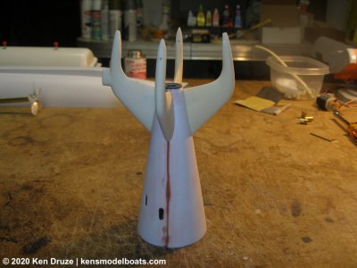
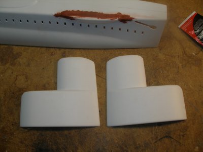
It starts out as bare styrene.

M PC030235.JPG

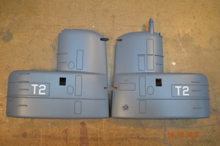
Without having to post tons of pictures, here is the final product. Some of lines you can see are scribed into the styrene. I never did scribing before. David Merriman III is one of the great fathers of the model submarine world. He was a navy torpedoman and he and his wife had a miniatures business that did modeling for movies and studios before CGI came around. He also was involved with models for Voyage to the Bottom of the Sea. I live in NJ and he in Virginia. I was connected to him through my Marlin build on RCGroups. So he encouraged me to do this scribing which added great detail to this detailless model. I only did some of the scribing, some major obvious ones. An outline pattern was cut in brass sheet, place on the sail, then cut into the styrene with a sharp pointed scribe. The holes on the inside of the scribed area represent bolts head that hold that panel in place. The panels being openings to area inside that need service. The rails and ladders are 0.030 brass rod/wire bent to shape and glued into drilled holes, held in the inside by drops of CA glue. David is a real character, busts your chops to get you to do better, love the guy, good friend.

N DSC_1133.JPG

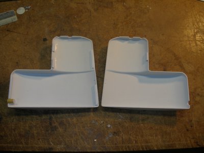
Bare inside of the sail.


O PC030242.JPG

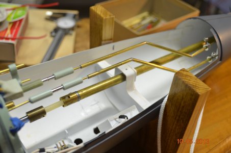
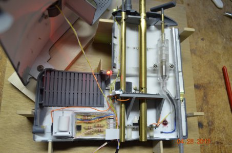
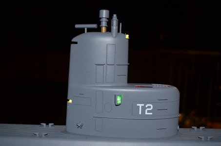
Oh my god! The inside of the sail. Keeping and explanation short is not going to happen. The lights, all models need lights. On the side of the sail is a red and green LED, port (left) and right (starboard) navigation lights. They are enclosed in a pop out chamber. There is an LED at the top in front of the periscope. There is and auxiliary light on the back end of the sail about 1/3 the way from the bottom. I also have a red LED to light up the bridge area. These LED's need a current limiting resistor which you can see in the waterproof box. So all of the LED's connect into that box. You see two brass tubes. The forward one is the periscope. It manually rides up and down in the tube. I can raise it all the way up and it locks in the up position so that when the model is submerged, I can run the boat with the scope above the water as a vsual to see where it is. It makes a tiny wake on the waters surface. But I rarely put it up. The larger tube is the snorkel. This also goes up ad down and locks in the up position. I use this all the time as it makes a bigger wake on te surface and can been seen easier. It also does a few other things. At the bottom you can just make out a white switch. I can twist the snorkel and push that switch and it turns on a motor, more later. At another level, twisted again and it slides a plate forward to open the pop out doors, at the same time a magnet activates a tiny reed switch which turns on power to the sail turning the lights and motor on. Retracting this turns everything off. Behind the snorkel you see a motor on an acrylic waterproof cylinder. This tiny motor makes the radar antennae spin. In that housing there is a magnetic coupler that protects the motor should a leaf get stuff on the antennae preventing it from spinning. The antennae and shaft would jam due to the leaf, but the motor will continue spinning. Before the waterproof box you see what is a float switch. On the surface, the LED's and radar would be on. When underwater, this float switch shuts them all off, after all they don't need to run when submerged. The silver aluminum tube on the right supplies air to the sub driver, more about that later.

The motor housing and the mechanics on the slide mechanism and the periscope/snorkel cutouts where made by my machinist friend Charlie who passed away. He will be sorely missed.


P DSC_1624.JPG

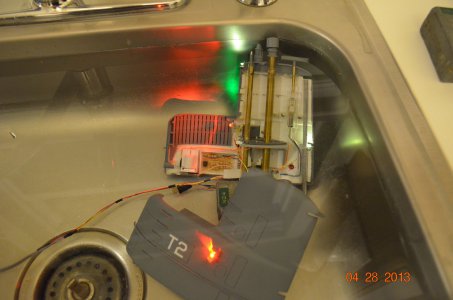
All wire connections had to be waterproof. Here I am testing all this in the kitchen sink. You can see the popped out red light on the port side.

P DSC_1778.JPG

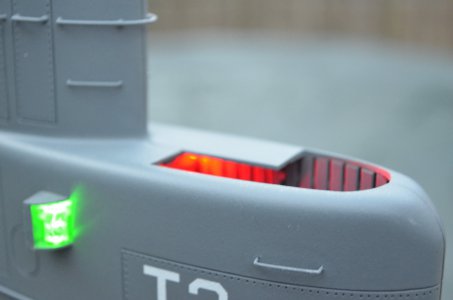
Showing the red light on the exposed bridge. Red so that it helps you with sight not looking at bright lights at night then into the darkness.

P1 DSC_1428.JPG

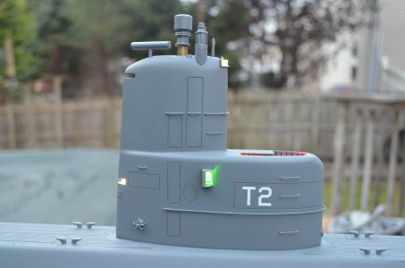
Finished. Nice detail if I say so myself. Could have added a lot more.

P2 DSC_1430.JPG

Finished

P3 DSC_1680.JPG

Having all this hardware in the sail does not help. It raises the center of gravity and causes problems while running the boat. I'll give more information on that later. Enough endless writing for now. Hope you like the pics and explanation.
 
I’m having flashbacks to some kind of twilight zone scene where the man puts so much detail into his models that he ultimately ends up trapped inside one…. !

Seriously though, your work is fantastic! I love seeing the amount of effort you’ve gone to in order to match the real thing. To my mind that’s what sets a true master apart.

Thank you for that! I can see that as well. My girlfriend and I had a good laugh about that statement. Although I'd have to be miniaturized like Fantastic Voyage, I'm way too big.

Every model I build, I learn something new, and improve upon my previous skills. I've spent a days making a part, in the end it is not right to me, and I trash it and start over. It also helps having other modeler friends to see what they do and how you can add that to your skills bucket.

DSC_1409.JPG
 
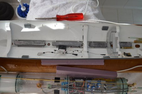
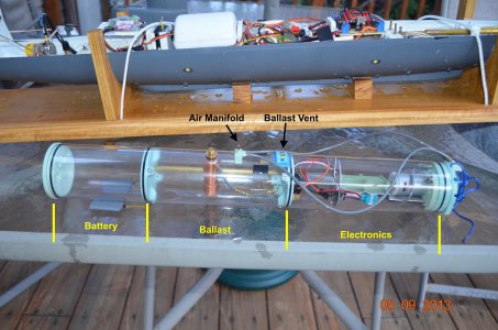
Once the model is built comes the more brain challenging part. In the top of the first pic in the boat you see a bunch of stuff. That was the original container that housed the electronics. It came with the Marlin kit and was impossible to keep water out. It was in the design. The term was coined 'sink-o-matic'. I won't get into it as it was discarded. David Merriman sent me one of his Sub Drivers (SD). This is an acrylic tube with sealed compartments. The center one is the ballast tank and can be flooded with water and also remove the water with air. The forward one held the battery. The aft one is for electronics. The ballast tank is enclosed with bulkheads with o-rings so no water passes the bulkhead. The ends are endcaps also with o-rings. A sealed brass tube connects the battery and electronics compartments to pass wires. As it came from David, it included the drive motor, ballast pump motor and ballast vent servo. More is needed, will describe below.
A1 DSC_0272.JPG

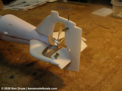
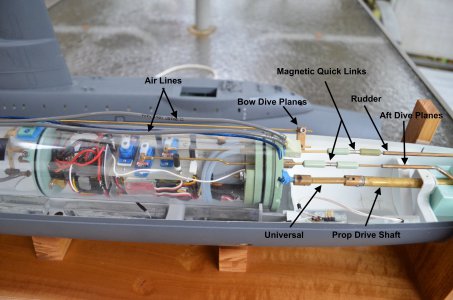
Here are some of the external connections to the SD. The universal is a modified Dumas universal, a common and easy universal drive shaft connection from Dumas Boats. The quick links make easy connections from internal push rods to control surfaces. Another feature designed by David.
B1 DSC_1899.JPG

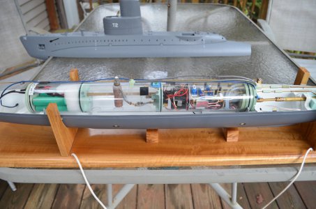
Here the SD is in the boat with all of the connections made. I'm testing in the pool at this point.
C1 DSC_1905.JPG

Close up of connections.

D1 DSC_0452.JPG

The push rods from servos and the drive shaft exit the aft bulkhead thru seals, o-rings, to keep water out. There are two brass tubes at the top for air connections.
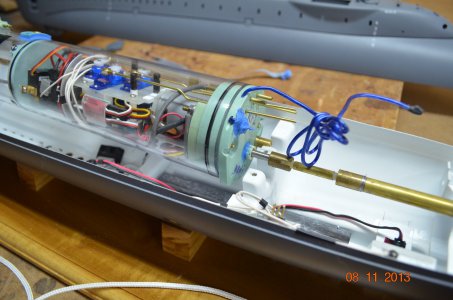
D2 DSC_0298.JPG

Parts here that do not come with the SD are the motor speed controller and servos. They need to be micro size servos. You can also see the motor, silver can to the right, and air lines above the motor. Like I said, beyond the SD, you need to buy and figure out how these things go together and where to put them. There are forums out there for help if you need help. The push rods from the servos exit thru the bulkhead/o-rings and end in a magnetic quick link.
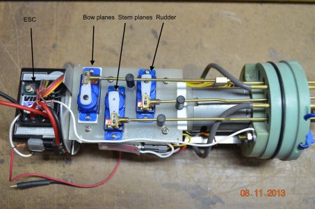
E1 DSC_0299 copy.JPG

Below the ESC is the radio receiver. The air lines connect to the ballast motor. The ADF2 does a number of things. Mainly it is a pitch controller. It connects between the receiver and servo for the aft dive planes. As the model is running submerged, it detects the the fore and aft pitch of the model and sends signals to the aft plane servo to adjust the dive planes to keep the boat absolutely level. When on the bench out of the water, if you lifted the bow of the boat, the pitch controller detects this movement and it will send a signal to the aft dive planes to move until the boat is level.
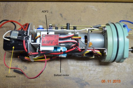
E2 DSC_0300 copy.JPG

Here you see the radio receiver with all of the servo connections. The ballast motor has air line connections. When you want to surface the boat, the ballast tank will be full, you move the transmitter stick which signals the receiver, it closes the ballast vent and activates the ballast motor which sends air into the ballast tank evacuating the water. The ballast motor and ballast vent share one channel on the radio system. The servo and motor are connected to the receiver with the y-cable connection. To submerge the boat, the ADF2 signals the ballast servo to open the ballast vent and allow water to fill the ballast tank. Again, you have to buy all these things and put them together. There are other manufacturers of some of these devices like the ADF2. Those is Europe probably have their own items they use there.
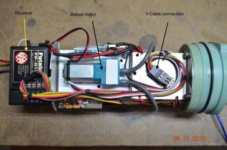
E3 DSC_0302 copy.JPG

There are other ways to setup model submarines. With this method the hull is free flooding with water. Water is kept out of the SD to keep the electronics and battery dry.
 
Last edited:
The final thing to do is trim the boat. This is usually done in a bathtub, some sort of test tank, or it can be done in a pool.
To keep the explanation simple, you would need to put weight low in the model, usually lead.

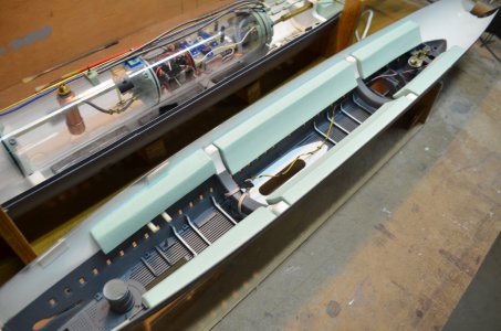
To trim the boat at the surface, you need to add foam just below the waterline so that the model sits at the proper waterline.

Then you blow the ballast tank so the sub sinks. Foam then needs to be added above the model waterline to get about one inch of the sail out of the water. If the sail sits at that one inch point, you are done.

It is a delicate balance between weight and foam. When trimming, rubber bands are placed around the hull and foam is inserted or removed in order to get the boat at that one inch point and to have the boat sit level.

Weight in the Marlin.
DSC_1159.JPG

And the foam
DSC_1201.JPG

How to operate the boat.
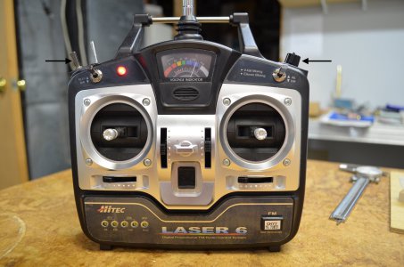
Right stick vertical up and down. Moves the bow dive planes up and down. When the model is submerged, the bow dives control your depth.
Right stick horizontal. Controls the rudder.
Left stick vertical. Controls the motor. Up forward, down reverse.
Left stick horizontal. Moved to left, fills the ballast tank with water, model submerges. Move to right, fills ballast tank with air, model surfaces.
Left arrow, toggle, turns lights on
Right arrow knob, aft dive plane manual control

DSC_2040.JPG
 
Last edited:
The ability to dive and resurface... I find that fascinating. I have been watching (thanks to this thread) some youtube videos on the process. Very cool.
 
I was just looking at my Youtube video's when I built this boat. Found one that I completely forgot about. Sorry but it's long, 30 minutes, and covers the pics I posted here and much more.


Here is a short one when I was testing the model in my pool.

 
Back
Top