I would ignore the 1340GT wiring and trying to port everything over to yours, the wiring/terminal connections are different. The picture is still too fuzzy to make out the contator specifics. My guess is they are 3 NO and one auxiliary which is a NC, the Teco model number would be CN-16 3atb if such. These should be a replacement
http://www.factorymation.com/CU-22-B6 as they have both a NC and NO auxiliary contacts. When replacing them you need to match up the red control wiring with the same terminals and auxiliary NC/NO connections. If there is a an additional contact block on the side of your CU-16's that could also be used, they switch the 24 VAC. Otherwise I would recommend trying to get the same contactor for the CN-16's as the model number you have this information would be on the side. You leave the CN-11's and all the other terminal connections to the board with the exception of the high voltage wiring. You could leave the current contactors rewire everything so it checks out and then replace the the CN-16 contactors at a later time. Often the upper body of the contactor is removable and can also be replaced separate from the coil assembly.
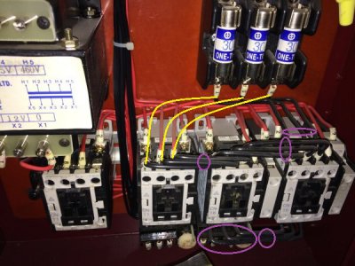
1. Remove the black high voltage black wires as shown in the purple circles. Power 240 VAC will come in to the R and S to the fuses, the power from the fuses (3 black wires connect to the reverse contactor) will be redirected to connect directly to the coolant contactor (shown in yellow). At the coolant contactor there are two red wires labeled R and S, either leave these connected to the coolant contactor or connect them directly to the R and S at the fuse connections, they provide power to the transformer. If needed, I recommend just replacing the coolant pump itself with a single phase model at a later date. You would power it from the R (U1) and S (V1) terminals.
View attachment 142878
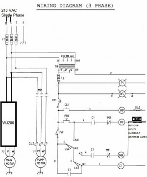
2. Remove the thermal overload OL1 on the forward CN-16 contactor and the black wires going to the main motor terminals U, V, W. There should also be two red wires going to the motor thermal overload OL1 and it should be a NC connection. These two wires need to be connected together after you remove the thermal overload.
View attachment 142879
After making the changes, I would power up the system before connecting the VFD to make sure the contactors are closing and the controls work as before.
3. Then Connect L1 on the forward contactor (one which had the thermal overload relay) to VFD P24 and T1 to VFD input 1 (forward) and Connect VFD P24 to L1 on the reverse contactor (one which had the thermal overload relay) and T1 to VFD input 2 (reverse).
4. Power going to the VFD could be picked up from the R and S terminals after fuses, or you can have separate fusing/breaker in another electrical box. Motor terminals from the VFD go directly to the same motor terminals as before on the motor. If the motor is running in the wrong direction, just switch any of the two motor terminal connections at the motor only. The VFD should have an external braking resistor, there is just too much momentum in the system for the internal braking resistor to handle. Programming parameters would be similar to what I posted for the PM1340GT, BUT the motor parameters (voltage, kW, poles) need to be set for your motor. The voltage is 230V A082 = 4 and the motor is 2.2kW H003 = 2.2, the default poles is 4 which is the same as your motor.
This is a general overview, it is hard to give specifics without seeing the system, hands on, so this is at your risk and assumes you have some general familiarity with electrical hookup.

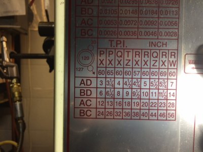
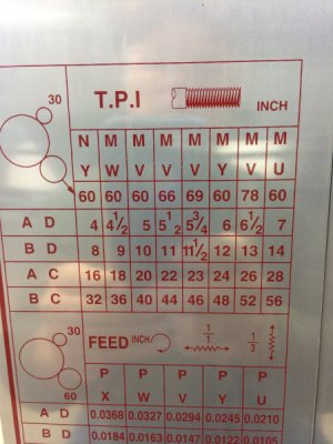
 taking a break from the shop. I only have a space heater out there, and it's 12 degree's. Concrete slab draws the life right out of you, especially already feeling ill. VFD should be here tomorrow. I'm rigging up a test run of the control board. Still just trying to understand how to make it all work. Going to take some pictures of the button panel next time I'm out there.
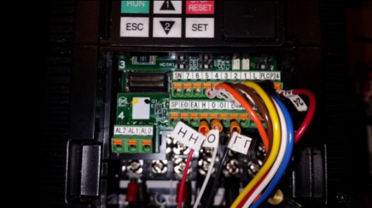
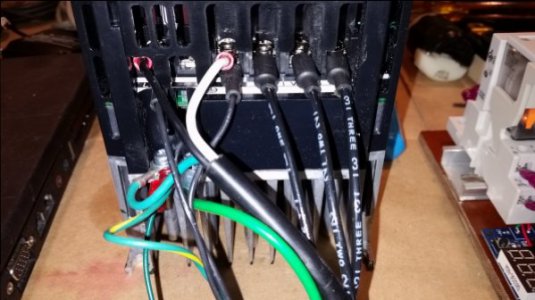
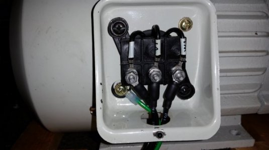
 My thinking was I would just write down the oil I needed for the lathe and go into a hardware store and get it... NOPE! I went in the store with my list as ISO 32, 46, and 68 non-detergent oil. Seemed logical to me but I knew I was in trouble when both the hardware stores I went to replied with "we have motor oil". Nothing I found had anything labeled non-detergent and for some reason ISO oil is very rare in my area (maybe it's a standardization in some place other then where I am?) I found 1 gallon of ISO32 oil at Ace hardware