Scroll bender switch problem in need of a solution ??

Taildrager

Registered
Registered
Joined
Jul 16, 2013
Messages
16
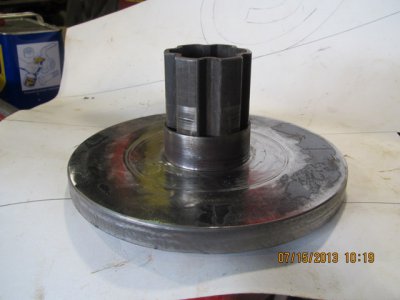
The plan was to use a band clamp around the yellow part . The band clamp would have a bump on it to activate a micro switch . By using the clamp it would be easy to time were it stopped by sliding the clamp around .
All was well until it dawned on me that the scrolls will be more than 360 degrees . The plan that went south was to use a foot switch going to a mag start with a hold circuit to a drum switch to reverse the motor . Is there any way to hold the foot petal down until the micro switch passes the first time then remove my foot allowing the hold circuit to hold until the micro switch stops it ?? Thanks Dommy i mean Donny:thinking::thinking: P.S . I thought i might add the scrolls i am bending are out of 3/4 solid round bar and i have a boat load of then to bend . The bender has the power to bend the bar stock 180 degrees around a 3/4 pin making a large hair pin. Having the capability of stopping the rotation at the same place will speed production and improve consist scroll shape
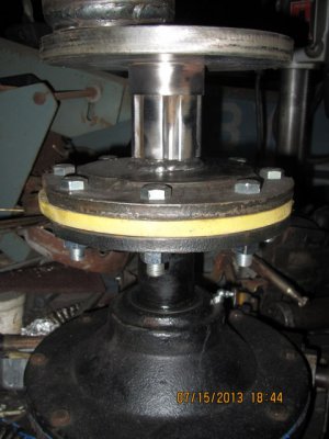
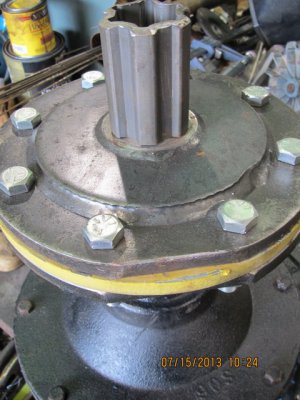
10-IMG_4207.JPG 09-IMG_4205.JPG 12-IMG_4209.JPG 15-IMG_4215.JPG 16-IMG_4216.JPG 17-IMG_4217.JPG 03-IMG_4199.JPG 06-IMG_4202.JPG
 
Last edited:
Put the stop switch wherever the ultimate stop point will be. Wire it parallel with the foot switch if it is a momentary contact style. They should be NC for the microswitch, NO on the foot switch. When you start the bend, have your foot switch closed, and the trip dog will open the microswitch with no effect. After it passes, you can release the foot switch, opening it. Then as the dog trips the microswitch this time, it is the only path, and will open and kill the contactor.

Clear as mud?
 
This may seem too simple, but couldn't you just step on the pedal again? Eg. 1 press/step = 1 revolution?

Of course there is a way to wire the switch so that it stops only if the pedal is not pressed.

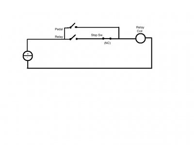
This circuit will do what you want. You will need a relay that has at least 1 extra, unused pole. Looking at your setup I am guessing that you have a 110/220v motor, so a three pole single throw (3PST) relay will do what you need. That specific combo is difficult to find, so a four pole, single/double throw (4PS(D)T) relay is what you will probably find. Make sure that the relay has a sufficient amperage rating for the motor you will be using.

(Sorry for the PaintCAD, I don't have my Electrical Design Software on this machine.... Also, the drawing shows DC power, not necessary, could be AC)
Latch Circuit.jpg
The lower Normally Open (NO) contact is on the relay, with the other poles that are controlling the motor. The upper contact will be the NO foot switch, and the NC contact will be the stop switch.

This circuit will run the motor as long as the foot switch is depressed, and only stop when the micro switch hits its stop, and the pedal is released.

Of course, an auxiliary stop button would be in order, as an Emergency Stop, preferably as a separate relay system/dead-man pedal.

Good luck! Don't hesitate to ask questions!

-Cody

Latch Circuit.jpg
 
I think were on the right track ! I know for a fact that this tool will bend my steel but for two reasons i didn't want to stop until the scroll was completed . One is having to start under load [ i realize i could momentarily reverse direction ] but more importantly i have the belief that they will turn out more uniformly with out stopping ?? The first solution looks like the one but the water is still a little cloudy the second may be just as good but the mud is a bit thicker it is my hope it will all become clearer when rereviewed ? Donny
 
They're basically the same solution, one described, the other also illustrated. Our explanations are just different ways of saying it, I believe.
 
It is not completely clear to me, where things are not completely clear to you. :lmao:

Starting under load, while not ideal, is entirely possible. The main concern is that the amperage at startup will be higher, therefore increasing the wear on the contactor. This is easily remedied by over-rating the contactor to double or even triple the required running amperage.

I tend to agree with you about not stopping until the scroll is complete. The circuit I provided will run as long as the foot pedal is depressed, and once released, stop at the designated point.

If you have a question about anything specific, please let me know how I can clarify. If you have the parts that you are planning on using, post a photo of them. It will help us to help you!

-Cody
 
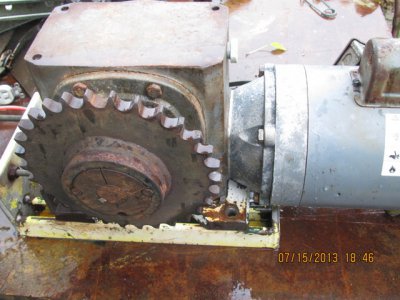
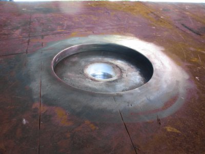
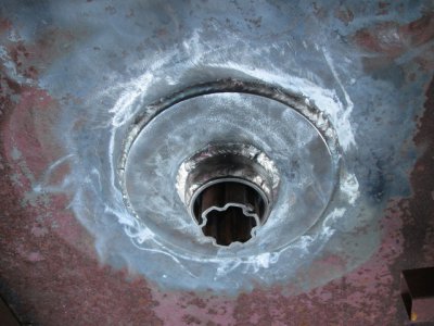
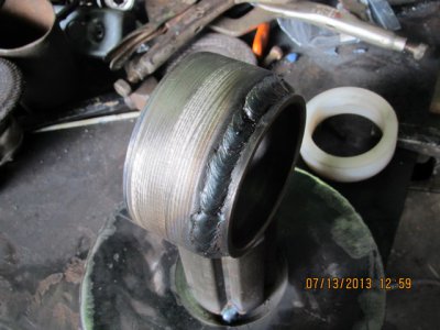
I will try to describe what your looking at in the photos .To start the bender gearing is mounted under one end of a 4 x 10 table with a 3/4 inch top. All components are salvage the small motor driven box is 1 hp 40 to1 with 1406 inch pounds of torque , large g/b is a worm drive 50 to 1 69,000 inch pound of torque . Geared to a final rpm of 2.5 . The coupler between the gear box an bender tooling is splined ag pto components . The one photo is of the under side of the table with the tooling disc dropped in . The top side photos show the recess were the disc drop in . The mandrills bolt or weld to the disc when not in use as a bender i will drop a blank in giving me a smooth top again . The hub has a nylon bushing and i also am using a 1/4 inch disc of nylon under the 3/4 in steel disc very quiet even under load . I will take some more photos of the gear box mounted when the camera comes home Donny
 
Of course, an auxiliary stop button would be in order, as an Emergency Stop, preferably as a separate relay system/dead-man pedal.
!

-Cody[/QUOTE]

I know its not a dead man but the drum switch would stop everything if switched off but i do like the idea of a emergency stop button very much. Would it require a separate relay or could everything be done with one of those ice cube relays ? Donny
 
I know its not a dead man but the drum switch would stop everything if switched off but i do like the idea of a emergency stop button very much. Would it require a separate relay or could everything be done with one of those ice cube relays ? Donny

As long as your components are rated for the amperage that you will be using, the E-stop switch could be wired directly inline with the supply power. If you choose to use a relay for the e-stop, you would not be able to run both the foot pedal control and the emergency stop on the same relay.

Though it is not good practice, a STOP (not emergency stop) button could be made by wiring an NC switch inline with the coil, AFTER the latch/footswitch circuit. It is technically not an e-stop, because it is not a redundant system, nor does it directly cut power from the machine. The real idea is that if the relay for the footswitch were to weld itself closed, the E-stop, being a separate system, would cut power to the entire device.

-Cody
 
Last edited:
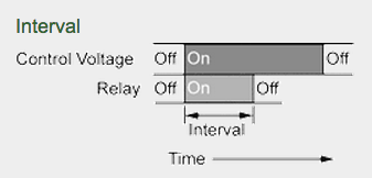
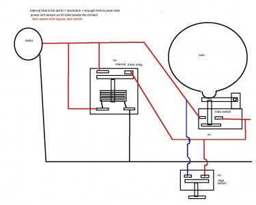
you can add an interval Screen Shot 2013-08-19 at 3.09.32 AM.png timer relay till you get past first bump/lobe/revolution

you other guys can verify this..i'm half asleep but i think i got it right..lol


also depending on how fast it is turning you may need a wider lobe in case the spool down drags past the lobe..


you can also make it do 2-3-4-5----- revolutions with the right timer..minutes/seconds

Screen Shot 2013-08-19 at 3.09.32 AM.png relay2.jpg
 
Last edited by a moderator:
Back
Top