Question G1003 change gears

The charts are a little different, but what I meant is that the actual gearbox ratios are the same. But, it looks like your right, there are a few actual differences

My phone won't let me open both charts side-by-side. Opening and looking at them 1 at a time, it's easy to miss the small differences.

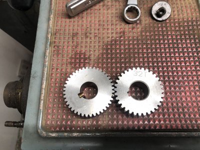
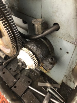
I have change gears in 28t, 30t, 32t, 46t, 50t, and a half dozen others. Knowing the actual gearbox lever ratios is very useful for calculating and cutting the weird, non-standard threads that occasionally pop up on proprietary designs.

I have a list of the actual ratios somewhere, I'll post it up in a minute.
 
Last edited:
Yea, looks like your correct. A couple slight differences.

 
Here are a few formulas you might find helpful, for creating a ratio chart for your gearbox and calculating thread pitches. It'll also help you determine which of your pitches are exact, and which are approximations.

If your lathe has an 8tpi inch leadscrew, which is almost certain given your 40/127/40 (1:1 ratio) gear arrangement for inch threads.

For each lever setting in your gearbox, divide the leadscrew tpi by the pitch given in the chart.

For example, A1 shows 4 tpi, so 8/4=2 A1 is a 2:1 ratio. 2 output shaft rotations per input rotation.
B1 shows 8 tpi, so 8/8=1 B1 has a 1:1 ratio
C1 shows 16 tpi, 8/16=0.5 so, C1 has a .5 ratio
D1 shows 32 tpi, 8/32=0.25, so the ratio for D1 is .25

Once you have those gearbox ratios, the metric side is easy.

For the metric, the 8tpi leadscrew pitch becomes 3.175mm(1/8")(25.4)=3.175mm

So, first the change gear ratio. Example 40/127x120/40=.944882

Now, the change gear ratio (.944882) times the gearbox ratio (lever setting A1 = 2). So 0.944882 x 2 = 1.89764 (this is the overall ratio, through both the change gears and gearbox

Now, multiply the ratio times the leadscrew pitch (mm). So 1.89764 x 3.175= 6.025007. so, A1 is a slight approximation, but gives you a metric pitch of 6mm.

Also, some or all of that extra .025007mm is probably rounding error from rounding to the nearest millionth.


Keep in mind that many of the thread pitches are approximations. Approximations are unlikely to ever be a problem.
For most threaded things, one or the other part is short. A short nut on a long shaft, or a short screw into a hole. Rarely ever would a 3foot long nut, or 3ft long screw be thread with engagement down its entire length.
 
Last edited:
Thanks again. It was pretty easy to turn the equations around and work out what I needed.... once I finally figured out how to modify the spreadsheet:rolleyes:. I'll try and attach the altered version on the off chance anybody finds themselves similarly ignorant in the future.

I should have a printed gear to try out tomorrow.
 
Awesome!

Now, when you get brave and wanna try cutting metric threads to a shoulder, using both your half-nut and your inch thread dial (don't listen to any of the guys who say it can't be done).

Watch Adom do it here. I've been using this method for 10+ years. It's fantastic!

He's like a robot though! I wouldn't dare do it @ 400 rpm. I go about a hundred rpm.
I like that technique. I’m sure I’ll f**k it up at first, but it makes all kinds of sense.
 
update. I went ahead and ordered the cheaper of the two gears from grizzly. Unfortunately it’s not a match. I believe the pitch is too coarse. It looks like I’ll have to actually learn to measure gears. My 40 on the left and grizzly 32 on the right.
 

Attachments

  • 1DEBB4EC-DA71-4869-A9A1-B79F60EE9DF2.jpeg
    1DEBB4EC-DA71-4869-A9A1-B79F60EE9DF2.jpeg
    3.5 MB · Views: 23
Continuing to update. I finally managed to figure out that the gears I need are 20° pressure angle, module 1.25. Semi uncommon I guess.:shrug: I made one up in fusion 360 and had my buddy to print it. Works like a charm! I’m pretty stoked. I’m going to do the 40, 32, and 30 tooth next. I’ll post them up on thingiverse when I’m done, and add a link here on the off chance someone else needs them in the future.
 

Attachments

  • EEC5026A-6DF4-4F4A-BF70-BB344F167947.jpeg
    EEC5026A-6DF4-4F4A-BF70-BB344F167947.jpeg
    1.6 MB · Views: 11
  • 7A17B573-00C4-4084-B0A6-65ED6508C2A9.jpeg
    7A17B573-00C4-4084-B0A6-65ED6508C2A9.jpeg
    1.3 MB · Views: 14
Continuing to update. I finally managed to figure out that the gears I need are 20° pressure angle, module 1.25. Semi uncommon I guess.:shrug: I made one up in fusion 360 and had my buddy to print it. Works like a charm! I’m pretty stoked. I’m going to do the 40, 32, and 30 tooth next. I’ll post them up on thingiverse when I’m done, and add a link here on the off chance someone else needs them in the future.


That's great!

Now that you can get gears in any tooth count you desire, there no limit to the feeds and pitches available.
 
That's great!

Now that you can get gears in any tooth count you desire, there no limit to the feeds and pitches available.
Yeah. It’ll be interesting to see what I come up with using your spreadsheet. I’ve already tried a few test threads on aluminum as some old rifle barrel stubs I have laying around.. They work ok, but kinda choppy looking. Long way to go before I do any real work.
 
Back
Top