Dear All,
I am attempting to build a model beam engine originally designed by Elmer Verburg. I downloaded the plan from John Tomlinson's site. I have made OK progress, but I am confused by some of the call-outs.
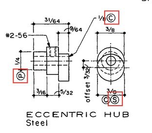
In particular, I don't know what the circled letters mean. For example, in the image below are circled C, S and P (outlined in red). On other parts of the plan you will also find a B.

Any help will be much appreciated. If this questions belongs elsewhere please let me know.
Cheers,
Tom
I am attempting to build a model beam engine originally designed by Elmer Verburg. I downloaded the plan from John Tomlinson's site. I have made OK progress, but I am confused by some of the call-outs.
In particular, I don't know what the circled letters mean. For example, in the image below are circled C, S and P (outlined in red). On other parts of the plan you will also find a B.

Any help will be much appreciated. If this questions belongs elsewhere please let me know.
Cheers,
Tom
Last edited:

