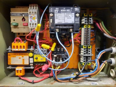
Price Point or Size for Better Quality?

Your analysis is spot on. Of course the VFD is an add-on. They started but never finished the VFD installation. I’m using the machine in a residential area so a VFD is necessary. I really want to use it as what you describe as “the wrong way.” I want it to function as designed. My Index mill does exactly that. I installed a VFD and connected it to the original barrel switch for fwd/rev/stop. I REALLY want the foot brake and clutch switch to operate as designed. If I have to choose, the foot brake is more important. At a minimum the foot brake would have to be integrated to shut down the VFD immediately. The Automation Direct VFD was much easier to configure than what I’ve seen so far with the ENC.

AI may be the “latest and greatest“ but I like hands-on control when machining.

I’m trying to understand what is technically/mechanically wrong with what you describe as “the wrong way“? My view of a VFD for this application is nothing more than to provide electricity. Is there a technical reason that it’s wrong or is it “the wrong way” because it CAN be done differently? I’m not especially interested in variable speeds. The geared head provides sufficient speed flexibility. How is giving up functionality a plus? Through the last 25 years of my career I saw lots of things getting done not because they needed to be done but because they could be done and not always because it produced the best outcome.

The coolant motor needs its own power supply (VFD) or a single phase motor. That’s a given.
 
Last edited:
There are others with more experience than I, but the issue with switching power generated by a VFD, is that high voltage surges are generated upon load switching. These voltage spikes often exceed the capacity of the VFD and cause permanent damage to it. By damage I mean the VFD becomes inoperable. The outputs of VFDs are designed to be permanently attached to the motor with no devices in-between. No contactors, no breakers, no switches. If that's not satisfactory for your use, then it might be better to look into alternative 3 phase power solutions, perhaps an RPC. VFDs are great, but they do require creativity and some rewiring. Hope this helps.
 
Congrats on the new machine. I highly recommend looking at posts by Mark Jacob’s on here @mksj

He’s done tons of conversions for members and always seems happy to help with advice.

If you want full function you will probably be miles ahead to just complete the VFD conversion correctly since the original electrical may be shot already and need repair even if you supply with 3 phase.

Lathes are often more complex than mills for conversion and/or troubleshooting. There’s nothing about doing the conversion “right” that will take away original features but a few can be added like proximity stops for threading and braking resistors for safety.

Cheers,

John
 
Dave, there is no problem wiring in the contacts off the switch that is associated with the foot brake, or of the “clutch” (probably a set of contacts with a handle near the apron?) and as many other stop / start features as you feel like - that is what the VFC’s control inputs are for. Do a temporary lash up, with the wiring external to the machine (look terrible, but correct electrically), then make it all pretty.

You are correct, that will not address the coolant pump. Leave the coolant pump as a someday down the road project. I’m a guy that loves coolant and have it on 3 machines (it isn’t like I need to spend a couple hundred dollars on a pail of soluble oil, that will last me a hundred years - I’m already set up) and I still don’t run coolant on the smaller manual machines, even though they have a working coolant pump. Coolant is a maintenance item and makes such a mess - work with squirts, sprays and brushes, set up a “spitter” etc.

It looks like you have landed a really nice lathe, enjoy it.
 
Dave, there is no problem wiring in the contacts off the switch that is associated with the foot brake, or of the “clutch” (probably a set of contacts with a handle near the apron?) and as many other stop / start features as you feel like - that is what the VFC’s control inputs are for. Do a temporary lash up, with the wiring external to the machine (look terrible, but correct electrically), then make it all pretty.
Just to clarify (for my own idle interest for now;)), it's my (limited) understanding that VFD's will have a number of inputs that can be used to control things like fwd/rev and braking (and obviously the frequency of the power going to the motor; which controls the RPM of the three phase motor I think; always been a bit hazy about this stuff) and I think that's what you said above. Is that right? :)
 
There are others with more experience than I, but the issue with switching power generated by a VFD, is that high voltage surges are generated upon load switching. These voltage spikes often exceed the capacity of the VFD and cause permanent damage to it. By damage I mean the VFD becomes inoperable. The outputs of VFDs are designed to be permanently attached to the motor with no devices in-between. No contactors, no breakers, no switches. If that's not satisfactory for your use, then it might be better to look into alternative 3 phase power solutions, perhaps an RPC. VFDs are great, but they do require creativity and some rewiring. Hope this helps.
You're absolutely right and I just didn't think about not having switching devices downstream form the VFD output.
 
John, Chipper:

Your suggestions are the correct path. I woke up today knowing that and I hadn't even read them yet. The wiring from the motor fwd/stop/rev off of the clutch shaft needs to be located and then enable the external inputs on the VFD. Need to verify that the switches work before doing anything else. I used the original motor control switch on my mill to control the fwd/stop/rev so this will probably be very similar. The VFD is on any time it's plugged in and the circuit breaker is on so I want to install a switch to control power to the VFD. There should be a parameter to enable an E-stop that will allow an unpowered coast to stop. Connecting that to the foot brake switch should allow the foot brake to operate as intended. As it sits, power is still pushed to the motor if the foot brake is activated.

I'm also going to at least consider doing all of this without getting as elaborate as I did on the mill. The electrical box and accessories for the mill probably set me back $500 including the Automation Direct VFD and braking resistor that I have not managed to implement successfully yet. I need to call AO for a little guidance on that.

The Chinese to English of the ENC manual uses some words that do not carry across well to English. Maybe having the well written AO manual open at the same time as the ENC will clarify the language. With a little luck the software will be a clone of the AO software or close enough that the AO manual really helps.
 
Is the coolant pump 3 phase also? I don't know much about VFDs but it seems like they can only drive one motor. Do people just replace the coolant pump with a single phase unit?
I've been going through figuring out the electrical for my planned backyard hobby shop. I've decided on a rotary phase converter rather than multiple VFDs.
Even if I only had one machine needing 3 phase, I think I'd still go the rotary converter route. Reason being, I'd be likely to acquire additional 3 phase items.
If you have access to a cheap 3 phase motor that is 3 times the HP of the largest motor you need to power, all the rest of the components to make a converter are (relatively) cheap.
 
Yes, the coolant pump is 3 phase, 1/8 hp. Its function is optional as I usually cut dry. I might even go with a coarse misting system and Kool Mist. This lathe has so much more capacity than my other one that everything changes.

My best understanding is that if there are multiple motors, they all have to be started at the same time and that is apparently OK. Turning a motor off and on while another is running can damage the VFD. My space is very limited so a rotary converter would be difficult to accommodate.
 
John, Chipper:

Your suggestions are the correct path. I woke up today knowing that and I hadn't even read them yet. The wiring from the motor fwd/stop/rev off of the clutch shaft needs to be located and then enable the external inputs on the VFD. Need to verify that the switches work before doing anything else. I used the original motor control switch on my mill to control the fwd/stop/rev so this will probably be very similar. The VFD is on any time it's plugged in and the circuit breaker is on so I want to install a switch to control power to the VFD. There should be a parameter to enable an E-stop that will allow an unpowered coast to stop. Connecting that to the foot brake switch should allow the foot brake to operate as intended. As it sits, power is still pushed to the motor if the foot brake is activated.

I'm also going to at least consider doing all of this without getting as elaborate as I did on the mill. The electrical box and accessories for the mill probably set me back $500 including the Automation Direct VFD and braking resistor that I have not managed to implement successfully yet. I need to call AO for a little guidance on that.

The Chinese to English of the ENC manual uses some words that do not carry across well to English. Maybe having the well written AO manual open at the same time as the ENC will clarify the language. With a little luck the software will be a clone of the AO software or close enough that the AO manual really helps.
Can you wire the original switches back to the VFD control board? The VFD I purchased for my air compressor has a control panel and I discombobulated the compressor box and used the controls in the VFD instead which eliminated the switch down line from the VFD....

To suppress the chuckles over my "Air Compressor" control panel (I hear it coming because some folks have no imagination), this is what I am talking about, the original panel:
20200818_232148.jpg
 
Back
Top