Possible fix for 3 jaw mount plate

Falcon67

Active User
Registered
Joined
Aug 19, 2014
Messages
225
The D1-4 Enco plate for my 3 jaw (came with the lathe) has just about wore out it's welcome. I've only been able to get it to seat with little runout twice. Not sure where it's binding, but short of buying a replacement plate from someplace like Grizzly, are there any possible fixes to help make the existing plate work? Thanks.
 
You are asking a really good question. There are some adjustments that can be made to get it to seat properly. I will take some pictures and create a little tutorial that may help. It will take me an hour or so.

Watch this space!!
 
It couldn't have wore out that fast. A couple things to check.

The spindle face should be ground but check for any high spots around the holes for the cam lock pins. Stone the high spots if any.

With the adapter mounted onto the spindle, shine some light betwen the mating surfaces, you should not be able to see any light. If you do, you'll have to remove material from the taper on the adapter.

Apply some bluing on the spindle nose & mount the adapter. Check if you are getting good contact there. If you aren't making any contact, you'll have to remove material from tbe adapter's mounting face.

If you do need to remove material from the adapter, take your time & in only very small amounts at a time.
 
FWIW I had one backplate that was like this on my adjust tru. The tapered hole that mated to the spindle was too small and the chuck didnt seat correctly. I tried stoning it in but lost patience with it after it continued to be a problem. I bought a South bend backplate from Grizzly and machine it to mate to the chuck no issues now
 
Nope, not worn out - it was fitted, but it was a pain to get on there. It does not want to pull up to the spindle correctly. There is a visible air gap in places. Adjusted pins, rotated chuck, moved pins around, measured pin height, etc. The spindle reads true (have not checked diameter) with .0005 runout. I have a 4 jaw D1-4 direct mount that goes right on with no issues, so I'm convinced it's the plate. Probably "that close" because last time it was on decently it was summer in the shop. Now in the 60s - no fit. I've gone as far as using a 12" breaker bar on the pins - can't force it into place.
 
Nope, not worn out - it was fitted, but it was a pain to get on there. It does not want to pull up to the spindle correctly. There is a visible air gap in places. Adjusted pins, rotated chuck, moved pins around, measured pin height, etc. The spindle reads true (have not checked diameter) with .0005 runout. I have a 4 jaw D1-4 direct mount that goes right on with no issues, so I'm convinced it's the plate. Probably "that close" because last time it was on decently it was summer in the shop. Now in the 60s - no fit. I've gone as far as using a 12" breaker bar on the pins - can't force it into place.

"Worn", yeah I guess I read that wrong. :)

For one of the backplates/chuck that came with my lathe that I kept, I skimmed the mounting face on the adapter. This resulted the same situation you described. What I did was mount the adapter in my 4-jaw & sanded the taper with the spindle under power to make my adjustment.

You did mention that you adjusted the pins but the adapter should mate to the spindle nicely without the need of the pins to "pull" it onto the spindle. Doing so when having too tight of a taper will result the adapter getting stuck on the taper & you'd have to use a mallet to unseat it.

If the gap is not that big, you may get away with making the adjustment the same way I did.
 
You may know what I’m about to show, but for the benefit of those who don’t know… Any modifications will be done to the chuck/backplate not to the lathe spindle. I am going to use the term ‘’chuck’’ to mean either the actual chuck in the case of a direct mount or the backplate depending on the style.

First check the spindle to make sure everything is OK there, it would be rare if there were problems with the spindle.

First let’s understand some of the pieces to the puzzle
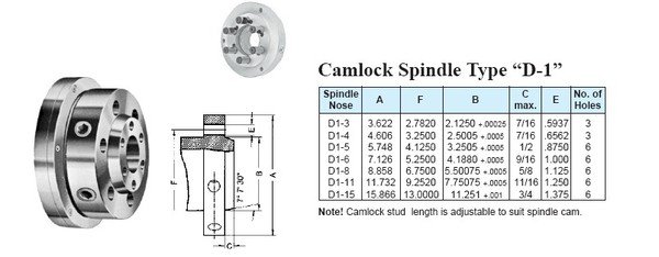
BISON-SPINDLE-NOSES-SPECS-2.jpg

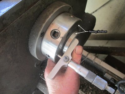
The mating surfaces. The nose taper should contact just before the flange pulls up tight, maybe 0.001 or so.
Get a measurement on the nose depth here that you will use later
IMG_0592.jpg


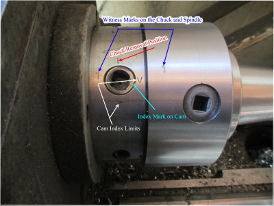
When the cam is tight, the cam index mark should always wind up between the Index Limits, if it does not, then you need to adjust the Stud Bolt depth
I have a witness mark (1) on my spindle, and I always mark my chucks once I get them dialed in so I can mount them in the same orientation each time.
IMG_0588.jpg


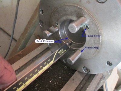
To adjust the Stud Bolt depth, remove the lock screw and screw the Stud Bolt in or out as needed, normally 1 turn either way will do. Then remount the chuck, and check the position of the Index mark, rinse/repeat as needed. The lock screw does not lock the Stud Bolt tight, it only keeps it from rotating too much, and the Stud Bolt will turn a bit.

Check the clearance between the Spindle Nose depth and the taper bore of the chuck. There should be a fair amount of clearance, the Spindle Nose should not bottom out.
IMG_0591.jpg


Now you can check the fit. First, do the mating flanges pull up tight? If not, then see below. If so then you can check the fit on the taper. The easiest way to do this is to mount the chuck. Then using a dial indicator, find the high point and mark it with a magic marker. Then smack the chuck with a deadblow hammer and see if the high point moves. Do this in each quadrant. If the chuck doesn’t move, then everything is mated properly and you’re done.
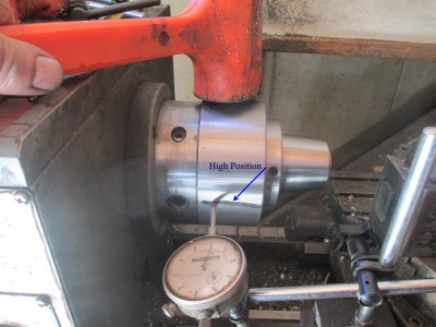

IMG_0594.jpg


If the chuck does move, then you need to remove some material from the flange to seat the taper a bit deeper. Without a gauge to check the relationship, it has to be done by removing some material, by facing the flange, just a thou or so, and then rechecking the fit on the spindle.

If the taper bore is too small and the flange won’t mate up then you will have to re-bore the taper. The taper is 7 degrees, 7 minutes, 30 seconds. So how do you set you compound to match that? The easiest way is to use a dial indicator on the Spindle Nose and rotate the compound while dialing in and out to get a zero reading through the travel.
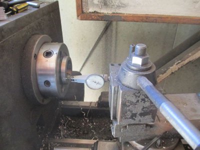
IMG_0596.jpg


Just take off a thou or so, then recheck. The easy way to set up is to mount the chuck on a shaft in another chuck. This also insures that anything you do will be in-line with the chuck jaws.
If you’re working on a backplate, then once the machining on the back is completed, you may have to refit the backplate to the chuck.
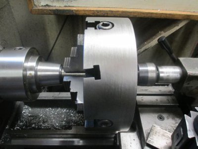
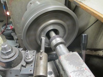
IMG_0329.jpg

IMG_0336.jpg

This is a long process, but in the end it will be worth it.
 
Last edited:
Thanks for sharing Jim!

Just curious, what is the purpose for those angled T-slots on your chuck for? I know many 10" & up 4-jaws come with T-slots but I never seen angled slots like that.
 
Thanks for sharing Jim!

Just curious, what is the purpose for those angled T-slots on your chuck for? I know many 10" & up 4-jaws come with T-slots but I never seen angled slots like that.

Neither have I. That is an example of an extremely ''high quality'' chuck from the Peoples High Precision Chuck Factory #3:confused:
 
Back
Top