Great "save" of a typical POS cheap tool! I bought a large drill press years ago that came with two Dayton vises; one is an XY unit. Now I'm going to have to "tune them up" with some of your ideas. Loving this forum and all the shared experience!
-
Welcome back Guest! Did you know you can mentor other members here at H-M? If not, please check out our Relaunch of Hobby Machinist Mentoring Program!
You are using an out of date browser. It may not display this or other websites correctly.
You should upgrade or use an alternative browser.
You should upgrade or use an alternative browser.
Polishing a turd or fettling a HF X-Y vise
- Thread starter mattthemuppet2
- Start date
- Joined
- Dec 17, 2012
- Messages
- 745
Ok, who will be the first to add power feeds and DROs to one of these vises?
- Joined
- Sep 28, 2013
- Messages
- 4,306
Great "save" of a typical POS cheap tool! I bought a large drill press years ago that came with two Dayton vises; one is an XY unit. Now I'm going to have to "tune them up" with some of your ideas. Loving this forum and all the shared experience!
well, I prefer "casting kit" to POS cheap tool, but it's 6 of one and 1/2 dozen of the other
Ok, who will be the first to add power feeds and DROs to one of these vises?
"DROs" are on the cards, at least in my standard cheap ass way, but need a couple of things doing first before they go on. Now a power feed, that's an interesting idea. Should be pretty trivial to do too as there's plenty of length left on the crank mounting stud. All you'd have to do is extend the crank handle flats and retaining nut threads towards the vise, put a larger nut on the thread and then lock it down with the original retaining nut. Then use a cordless drill with a socket that fits the larger nut. Simple.
Then again, 6in isn't a whole lot of distance to crank a handle
- Joined
- Dec 17, 2012
- Messages
- 745
Then again, 6in isn't a whole lot of distance to crank a handle
Just 6" for a vise, but a big leap toward CNC :biggrin:
- Joined
- Sep 28, 2013
- Messages
- 4,306
I have difficulty working out diameters, I don't think CNC is on the cards any time soon 
Got another bit done last night. The guide rod for the vise jaw was ~0.004in high at the fixed jaw end, so I could get the moveable jaw equally tight at either extreme. So I took the top half of the vise to pieces and used my dremel to carefully grind down the guide hole for the fixed end, take a little bit off one end of the bore in the jaw (so that it would sit flat) and a teeny bit off the crank end to get rid of any slack in the moveable jaw. I then drilled and tapped a hole for a set screw at the fixed end to push the guide rod down.
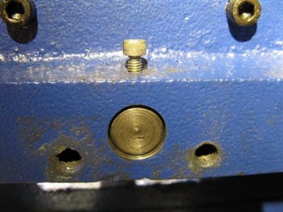
needed a little bit of paper to take up the slack at the crank end
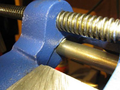
snugged up the adjustment screws a touch on the moveable jaw and now it is equally tight at both ends of the travel, with no discernible wiggle or gap between the vise and the jaw. I was pleased as punch!
here's the thrust bearing on one of the axis
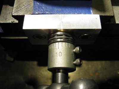
Next up, extra gib screws and brass gibs
Got another bit done last night. The guide rod for the vise jaw was ~0.004in high at the fixed jaw end, so I could get the moveable jaw equally tight at either extreme. So I took the top half of the vise to pieces and used my dremel to carefully grind down the guide hole for the fixed end, take a little bit off one end of the bore in the jaw (so that it would sit flat) and a teeny bit off the crank end to get rid of any slack in the moveable jaw. I then drilled and tapped a hole for a set screw at the fixed end to push the guide rod down.

needed a little bit of paper to take up the slack at the crank end

snugged up the adjustment screws a touch on the moveable jaw and now it is equally tight at both ends of the travel, with no discernible wiggle or gap between the vise and the jaw. I was pleased as punch!
here's the thrust bearing on one of the axis

Next up, extra gib screws and brass gibs
- Joined
- Sep 28, 2013
- Messages
- 4,306
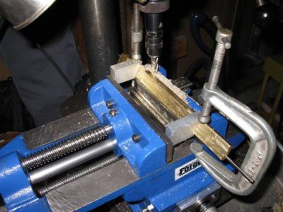
made my first chips last night! Started on the new brass gibs. Not sure if they'll make any difference, but it'll be a good way to get used to "milling" on my drill press and a big change from the Accupath monster I've used at work.
I used my weedy benchtop bandsaw to cut the strips from a piece of brass (I think) scrap. As you can see, the strips bowed out noticeably, as predicted by someone other than me
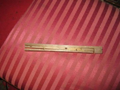
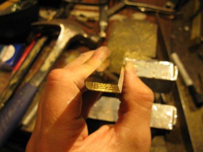
carefully bent them straight in the vise checking them against a parallel (the only certifiably flat thing I have)
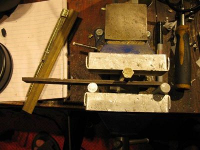
cleaning up the end, which will be slotted for a gib retaining screw (hole to be tapped into the end of the cross slide). That'll extend the gib a little bit for more support too.
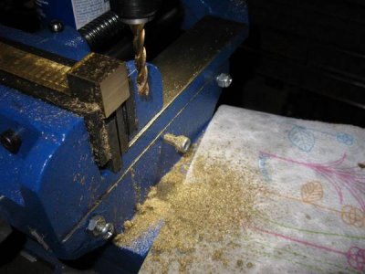
then the back side of the gibs need to be milled to the correct thickness and milled at an angle to the correct height. I'm aiming for a loose slip fit in between the vise halves to make them as thick as possible.
I used my weedy benchtop bandsaw to cut the strips from a piece of brass (I think) scrap. As you can see, the strips bowed out noticeably, as predicted by someone other than me

carefully bent them straight in the vise checking them against a parallel (the only certifiably flat thing I have)

cleaning up the end, which will be slotted for a gib retaining screw (hole to be tapped into the end of the cross slide). That'll extend the gib a little bit for more support too.

then the back side of the gibs need to be milled to the correct thickness and milled at an angle to the correct height. I'm aiming for a loose slip fit in between the vise halves to make them as thick as possible.
- Joined
- Sep 28, 2013
- Messages
- 4,306
- Joined
- Sep 28, 2013
- Messages
- 4,306
small update - first gib finished
this has taken a while a) because it was a b!tch to do and b) we're getting ready for our move, but I've finally finished one of the gibs
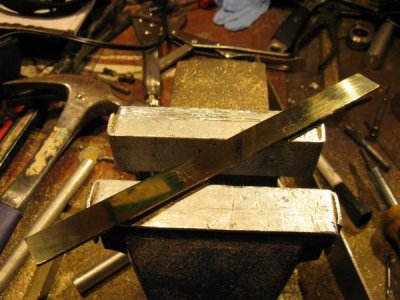
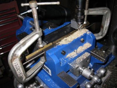
gib screw holes were done with a ball end mill and the gib mounted in a slotted piece of alu plate in the vise at the right angle
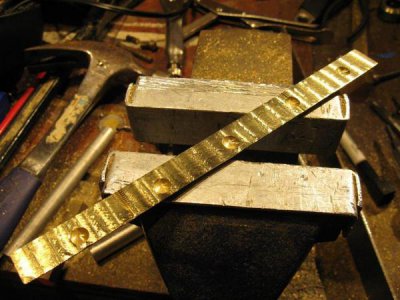
face was sanded 320-400-800-2000 (didn't have any sheets big enough between 800 and 2000), then polished with mother's mag polish
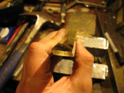
the other one is almost finished, but I need to turn the center piece on the vise around to drill the extra screw holes and mark the gib screw locations. Getting there!
this has taken a while a) because it was a b!tch to do and b) we're getting ready for our move, but I've finally finished one of the gibs

gib screw holes were done with a ball end mill and the gib mounted in a slotted piece of alu plate in the vise at the right angle

face was sanded 320-400-800-2000 (didn't have any sheets big enough between 800 and 2000), then polished with mother's mag polish

the other one is almost finished, but I need to turn the center piece on the vise around to drill the extra screw holes and mark the gib screw locations. Getting there!
- Joined
- Sep 28, 2013
- Messages
- 4,306
hah, if only!


