Polishing a turd or fettling a HF X-Y vise

I don't know if this will help you or not Eric, but I spent quite a few hours filing down the high spots on the various sliding surfaces as well as lapping and polishing the steel gibs and it slides very nicely now, to the point where I can tighten the gibs to almost binding and then a tiny turn will lock it up. The idea was to knock off any high spots and increase the mating surface area to reduce any unwanted movement. No idea how it'll all work in practice yet as I hit a snag last night assembling the last lead screw, but hopefully I'll know soon enough.
 
Hi Matt. Thanks for the reply. How did you determine the high spots? I was not having too much luck with that oily prussian blue paste that I bought at the auto parts store. It said that it was non-drying, and that seemed to be the problem. I just got a tube of Dykem scraping blue to see if that would work better.
 
nothing as professional as spotting :) I used a big flat file and took off the ridges so it looked the same all over and a 60deg triangular file for the dovetails. I didn't take the surfaces down to flat, I left the valleys there to hold oil and provide a visual reference. I know, I know, that'll have any self-respecting machinist curling their toes, but I don't have the measuring tools to do any better and it seems to have worked out okay. The gibs I used a big sanding block and went from 320 to 2000 grit sanding them flat on the block in a figure of eight motion, then I polished them with Mothers. That and cleaning out the paint overspray alone made a big difference.

I finally put it together last night after hitting a snag the night before ("poor snag, was it hurt?" asked my wife :)). I'll post up some pics in a bit after I've set up an experiment.
 
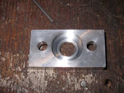
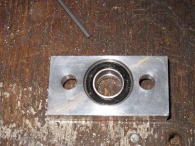
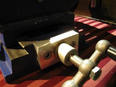
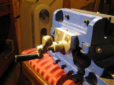
alright, bottom axis time. Same material as before, but I used a smaller OD bearing (from my front mtb hub of all things) so that the end plate would clear the sliding bit above it (the top axis doesn't :().

IMG_3266_zps54f9df68.jpg

IMG_3267_zps2ae45a54.jpg

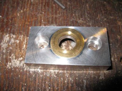
IMG_3265_zps4bd58820.jpg

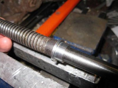
The bearing had a larger ID than the other one, so I had to make a little top hat spacer/ bushing to fit the lead screw
IMG_3263_zps8670c171.jpg

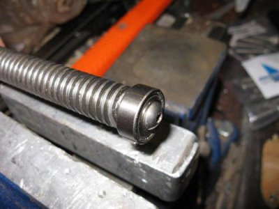
And, largely as a placebo (I don't think it actually does anything), I added a small bearing to support the other end of the lead screw. I ground a small raised pad on the end and drilled/ tapped a hole in the middle. Well, sort of in the middle, as I'm completely useless at drilling precise holes despite using a punch, then a center drill etc. Anyway, I deliberately used a bolt with a narrower diameter than the ID of the bearing just in case this happened, so it still rotates nicely
IMG_3264_zpsa5c99db8.jpg

Bottom axis
IMG_3269_zpsa9c97888.jpg

Top axis
IMG_3270_zps589dadaa.jpg

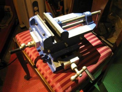
Finished!
IMG_3271_zpsb3d7f067.jpg

Just have to figure out a way of attaching it to the drill press table. I might put it on a slant until I can scrounge some plate to make an engineering plate as suggested above. Now I need to make an appropriate bushing for the collet chuck George gave me :)
 
Thanks for posting this... I have one I need to polish. Mine is mounted to the drill press table with clamping step blocks from my mini mill collection. That part works great.
 
glad I could help and thanks for the tip on using clamping blocks, I'll have to see if that'll work.
 
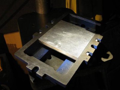
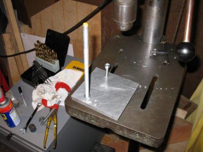
Almost finished making an engineering plate. As the slots on the table were narrower than the inside of the vise casting I thought I'd try an internal plate, which Rob in the machine shop graciously helped me make in exchange for beer and lots of good coffee. The idea was somewhat trivial, but it took a lot of set up to square, drill, tap and angle the plate then mill and drill the holes for the bolts in the casting hold down slots. He also helped me mill the middle casting a smidge so that the new end plate cleared the casting.

The plate sits about 1mm inside the casting, so hopefully won't affect the flatness of the base.
IMG_3275_zpsda22c88a.jpg

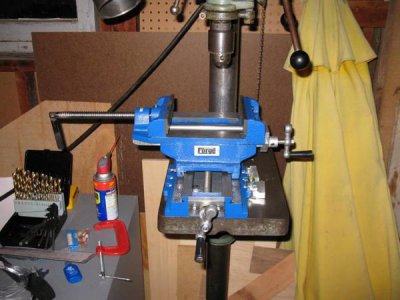
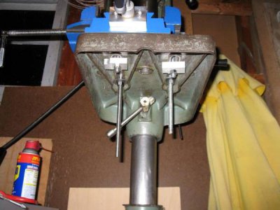
A lot of head scratching and fiddling ended up with the vise being set way over to one side of the drill press table so that the vise jaws are centered under the chuck when the top slide is centered on the vise. That means 2 bolts through the engineering plate and 2 bolts clamping the side of the casting using some alu blocks as step blocks. All that head scratching meant I only had time to drill and tap two holes :)

IMG_3278_zps8af330b7.jpg

have to prepare for a couple of job interviews this week, so this'll probably get done at the weekend.
 
it's now installed on the drill press, although I still need to do some fiddling and fettling. I'm going to try and "tram" the vise in with my dial indicator and shim stock, so it's as perpendicular to the spindle as possible. Might also get some proper thrust bearings, but we'll see.

IMG_3280_zps54767a61.jpg

up its skirt, so to speak

IMG_3281_zps3af1df5f.jpg

the extra long bolts at the back are there to hold a bodged up bracket which will hold a cut up baking tray chip pan. Once that's sorted, I'll cut the bolts down. Getting there, but I ran out of puff for a little bit and spent some time on the collet instead.
 
Looks good. I got mine polished following your instructions: it slides real nice with no detectable side play. I made bronze bearings for it. Now I just need to scare up a 7/16-UNF die and some Bellville washers so that I can replace the crappy setscrew collars with nuts and preload the bearings.

Are you going to add dials?
 
Back
Top