PM Research #7 It Begins

One thing I have already noticed is I am tasked to come up with ways to hold the base securely and how To set up and make measurements on a part that is odd shaped.
Most of the measurements cone off the crank shaft center position and height.
The pics show how I came up with finding the position of the crankshaft center and how to measure the cylinder mounting surface off the crank center.
Once I mill the faces to the correct depth, I can measure the cross head mounting holes and so on.
Right or wrong, this Is the way I’m measuring.
I guess I could have used the DRO on the mill now that I think of it.
 

Attachments

  • C54F7E7A-E816-4403-8E65-D12E607C7D2E.jpeg
    C54F7E7A-E816-4403-8E65-D12E607C7D2E.jpeg
    910.1 KB · Views: 51
  • B8843801-16DD-425B-9BDF-E29F978962F3.jpeg
    B8843801-16DD-425B-9BDF-E29F978962F3.jpeg
    1.1 MB · Views: 50
  • 0BC29B44-78F4-4DA8-9694-E22C5246FCF3.jpeg
    0BC29B44-78F4-4DA8-9694-E22C5246FCF3.jpeg
    1.1 MB · Views: 33
  • 543FE52F-9F6F-4D55-92D9-9AC86DFA9B2B.jpeg
    543FE52F-9F6F-4D55-92D9-9AC86DFA9B2B.jpeg
    1.6 MB · Views: 32
  • 850E6303-9A13-4A90-AA1D-22035C6017F5.jpeg
    850E6303-9A13-4A90-AA1D-22035C6017F5.jpeg
    1.6 MB · Views: 34
I assume the notches in your test crankshaft are identical.

Eric
 
I assume the notches in your test crankshaft are identical.

Eric
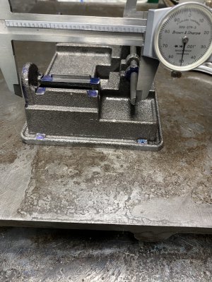
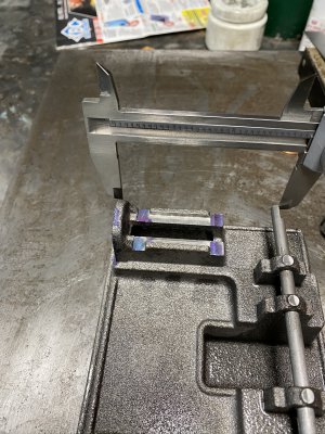
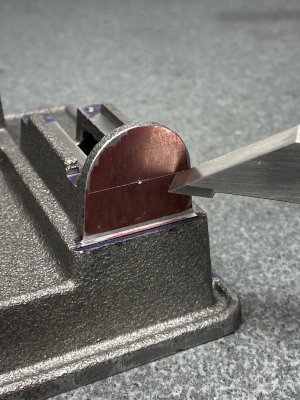
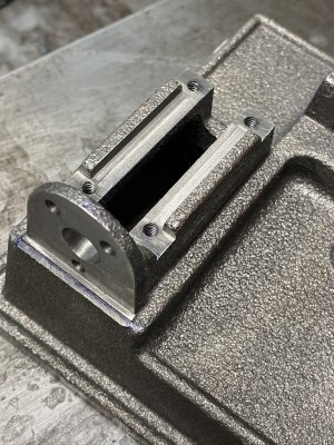
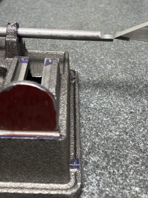
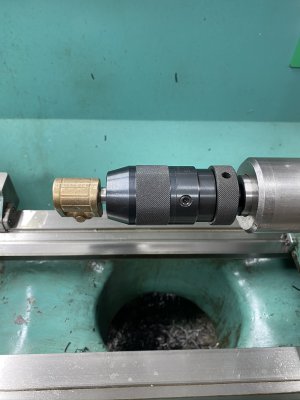
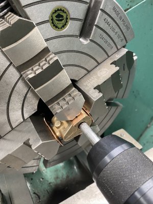
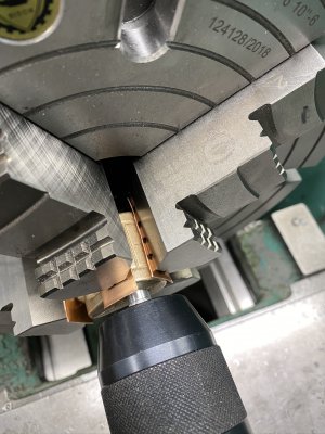
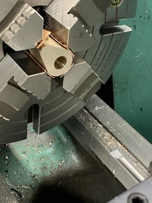
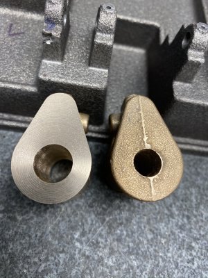
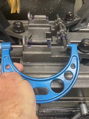
According to my micrometer, yes sir. I used a machinists square on both ends to verify I had a 90 degree attitude.
The .125 depth of cut was my goal.
Next step is to try to face the cylinder mounting surface to the exact 3.250 distance. With a micrometer and a DRO, it shouldn't be too tough.
Having never done a steam engine model before, I'm trying to be as accurate as I can be. The cross head deck came out very good according to the measurements I took with my surface gauge.
I'm learning quite a bit.
In fact, this is the first time I have worked to plans.
 
Looking good so far! I think making chips is the best way to learn. It certainly taught me more than just reading about it.

Eric
 
Success, at least one side. During the week I only get a few minutes here and there. The three day weekend coming up is supposed to be 111 degrees. I'll be in my air conditioned shop or in the pool.
The pic shows a micrometer measuring the dimension. It came out to 3.250". A DRO sure helps.

Having the cylinder faces complete, I was able to measure and center punch the cross head guides retaining holes.
 

Attachments

  • mic.jpg
    mic.jpg
    63.9 KB · Views: 28
  • ABED9B2E-192D-4CE2-A0DD-7334ABD59C26.jpeg
    ABED9B2E-192D-4CE2-A0DD-7334ABD59C26.jpeg
    848.2 KB · Views: 21
  • 26141BCF-3C8B-4682-80ED-CE35DCF70859.jpeg
    26141BCF-3C8B-4682-80ED-CE35DCF70859.jpeg
    1.2 MB · Views: 25
Last edited:
Just a bit more work on the base. Then I move on to the brass castings.
Saturday morning was productive.
 

Attachments

  • B48D954D-FC9B-4A3F-B4B3-9420C95EBCC1.jpeg
    B48D954D-FC9B-4A3F-B4B3-9420C95EBCC1.jpeg
    1.7 MB · Views: 18
  • 80DA12E2-20F7-467D-9187-7018AA2F9A26.jpeg
    80DA12E2-20F7-467D-9187-7018AA2F9A26.jpeg
    2 MB · Views: 19
  • A201B7CE-C925-40E4-AD74-25B7B26459BD.jpeg
    A201B7CE-C925-40E4-AD74-25B7B26459BD.jpeg
    2.1 MB · Views: 19
  • 32AB20DA-C25E-4507-BBCC-B9AA2BE59C56.jpeg
    32AB20DA-C25E-4507-BBCC-B9AA2BE59C56.jpeg
    847.5 KB · Views: 20
  • 8A187F0A-E174-474D-81DD-80E396889394.jpeg
    8A187F0A-E174-474D-81DD-80E396889394.jpeg
    962.1 KB · Views: 15
  • 5BE54542-31EB-4A08-9BBE-5D1E095A4168.jpeg
    5BE54542-31EB-4A08-9BBE-5D1E095A4168.jpeg
    817 KB · Views: 15
  • C0E9C366-F6C8-4674-AD5B-F44AA725DAD0.jpeg
    C0E9C366-F6C8-4674-AD5B-F44AA725DAD0.jpeg
    1.8 MB · Views: 23
Last edited:
I learned a few things so far.
I saw this method of lining up the cylinder by making a mandrel guide and using the tailstock to assist in the proper attitude in the four jaw chuck. Unfortunately this assumes the castings are consistent.
The one I turned is off .040“ and the unfinished bore is .025” off center.. I think it would be easier without the hole, lay it out, center punch and indicate center off the tailstock with a dead center.
In hind sight, I should have double checked and made the adjustments from there.
Now I’m not sure what to do.
It is a model after all.
I could order a new casting.
The next one will be better.
 

Attachments

  • 4816EDEE-F189-434D-8E3D-8E6CCD097976.jpeg
    4816EDEE-F189-434D-8E3D-8E6CCD097976.jpeg
    989 KB · Views: 20
  • BB41D0C9-0038-4BA3-8AD3-EF1E62FD4D4F.jpeg
    BB41D0C9-0038-4BA3-8AD3-EF1E62FD4D4F.jpeg
    549.8 KB · Views: 21
  • D4AF5196-4496-4F5B-8BA7-3AA9A1EA951E.jpeg
    D4AF5196-4496-4F5B-8BA7-3AA9A1EA951E.jpeg
    855.2 KB · Views: 20
  • F58B57AD-0DF3-4463-82C6-CC46FDA402F8.jpeg
    F58B57AD-0DF3-4463-82C6-CC46FDA402F8.jpeg
    834.6 KB · Views: 20
  • 793AD9B9-FB58-424F-9D89-E98C0C2D4856.jpeg
    793AD9B9-FB58-424F-9D89-E98C0C2D4856.jpeg
    640.4 KB · Views: 23
  • FA851D81-09F4-4878-B205-A35E3BBEA76A.jpeg
    FA851D81-09F4-4878-B205-A35E3BBEA76A.jpeg
    821.7 KB · Views: 32
I contacted PM Research. I would not be happy jury rigging this cylinder to work. They can have a new cylinder delivered to my door step for less than $20.
Done!
Now I need to get this right.
 
When I made my #5 I centered the cylinder bore using the outside of the casting.
 
Back
Top