PM-1236 motor issue

With the VFD control, you can run the speed very low or to a stop when threading, then reverse and pick up the speed to back out. Essentially, you can set it like a JOG button, but not a big deal to add a F/R JOG switch. When wiring, I usually use 8 wire cord, so I have some spares (like for a 2 stage breaking switch). I recommend using a LED power indicator light (~30 mA) because of the low power draw, as the VFD bus can only supply 100mA (relay is about 60 mA). Also be aware that the relay connections in the socket are often different then relay itself.

I use a 22mm LED lighted switch for my JOG button, the LED is connected as shown in the diagram to indicate power is active. Use shielded cable for the speed pot and the input terminal controls, ground at the VFD. It is also recommended to use shielded cable between the VFD and the motor.
 
With the VFD control, you can run the speed very low or to a stop when threading, then reverse and pick up the speed to back out.

I wanted to point out, that you have to be careful doing this. Unless the motor is specifically designed to be used with a vfd (inverter duty rated), you can damage it buy running it to slow. Basically You can overheat it, because its cooling fan isn't running at it's designed rpm.

I've head a lot of people recommend not going bellow 50% of the rated frequency and even then that's assuming your not putting the motor under heavy load.
 
This applies to prolonged use, in this case you are only using the motor for a short period of time (if that). I normally use a range of 30-90Hz on my PM1340GT with no problems on a non-inverter rated motor. The Leeson metric motors he is using is inverter rated, very nice metric sized motor at a reasonable price. As you mentioned TEFC should not be run for low speed for a prolonged period of time, as opposed to TENV motors.
 
This applies to prolonged use, in this case you are only using the motor for a short period of time (if that).


That's why I also mentioned the cavet about how hard you are working the motor. this page has a good example of another senario that people need to be aware of.
http://ecmweb.com/design/mating-new-variable-frequency-drives-existing-motors

Using a VFD, with fundamental frequency being reduced to achieve lower speed, the voltage also is reduced in direct proportion to the speed reduction. As mentioned earlier, a 460V motor at half rotor speed will have 230V across its lines. Thus, if the motor's rating is 100 hp at full speed, its output would only be 50 hp at half speed.
Certain loads, like lathes and grinders, require constant horsepower throughout their operating speed range. Let's assume a VFD is serving a 20-hp lathe motor that's operating at a 25% reduction in speed (3/4 rated speed). The lathe's rotating chuck, which holds some material being worked by a cutting tool, will need constant horsepower over the entire speed range being used. If speed is reduced by 25%, voltage will be reduced by 25%. For the motor to maintain constant horsepower output, it will draw 33% more current (4/3 of normal amperage). Because current produces heat (primarily [I.sup.2]R losses), the motor will have to have sufficient thermal capacity to handle the extra amperage.


with all that being said, the main thing to remember is that a VFD on a regular motor will work well for a long time, as long as you are relastic about what you are asking it to do.
 
Dan_S,

You seem to have a very good understanding of VFD's. In your opinion, what are reasonable upper and lower frequency settings?

AJB
 
You seem to have a very good understanding of VFD's. In your opinion, what are reasonable upper and lower frequency settings?

As my Uncle used to say, I know just enough to be dangerous. :))


From what I have read, it has a lot to due with how much abuse the motor in question can handle. I have heard of people using 30hz - 90hz, and I've also heard 45hz - 75hz for a 60hz motor. Hopefully someone with more knowledge than me will chime in and explain how to determine whats a good range.
 
I'm pretty much in agreement with Dan_S. 30 to 90 Hz is where I normally run mine. Sometimes for very light cutting I'll go to 15 Hz for very short periods of time. A 1800 nominal RPM motor is generally safe to run to 120 Hz, but I would not do that with a 3600 nominal RPM motor. I do the large speed changes with the belts/gears, then use the VFD to fine tune the speed.
 
Dan and Jim,

Thanks for the VFD advice. I just installed my first one on a 2hp lathe and set the range for 50-70hz. I felt like this was very conservative but I wanted to protect my motor. Based on what you guys are saying I may increase the range a bit.

AJB
 
The context of the low speed use was for jogging direction, whether this is done by hitting the JOG button or using the variable speed pot is irrelevant. It would be unwise to operate the VFD motor at low speeds for any length of time.

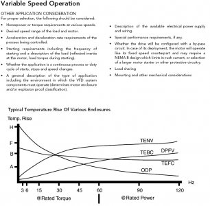
Just to add some clarity on the discussion of 3 phase motor speed ratings with a VFD, this is specific to the machine design specification, application requirements and the motor/VFD used. We are talking about non-CNC hobby application type lathes that are not run in continuous mode at full load. If you look at most factory supplied lathes in the 12-14x40 range with variable speed VFD operation, they usually have two mechanical speed ranges to cover a 50-2500 RPM speed range (example: SHARP 1440V with a 3HP motor). In most cases the motor is up-sized by 50-100% to cover the broader operating range needed with 2 mechanical speeds. The VFD operating RPM range is ~10 fold. There is no free lunch, and one needs to understand that horsepower drops off in a linear fashion below the motor's base speed, and torque falls off above the motor's rated speed in a somewhat linear fashion to 1.5-2.0X the motor's base RPM. That being said, if you have a 6-9 speed lathe, as you go shift to a lower speed range you amplifier the motors rotational force to the lathe shaft. There is also a big difference power requirement difference if your threading a 1-2" rod vs. turning a large diameter piece.

Regarding operating speed of most inverter rated 3 phase motors, there are many factors that come into play (electrical and mechanical). In my discussion with motor manufactures, many rate their 1800 RPM 3 phase inverter 2-5Hp motors to 1.5-2X their base speed. Vector duty motors are usually rated a bit higher "Vector Duty and Inverter Duty motors from Marathon Motors are designed for operation at 150% of rated load for one minute, up to the base speed of the motor (overload capability declines to 100% as the motor reaches maximum constant HP speed). These motors accommodate constant horsepower operation to 1-1/2 to 2 times base speed, subject to the motor's maximum safe mechanical speed limit." Most 3 phase inverter rated 3 phase motors have constant torque range of at least 10:1, so in theory would allow constant torque down to ~200 RPM. http://www.marathonelectric.com/docs/2014-SB300.pdf

Variable Speed Motor Operation.jpg


http://www.vfds.com/blog/vfd-buying-guide
"Generally speaking, a motor should not be run at any less than 20% of its specified maximum speed allowed. If it is run at a speed less than this without auxiliary motor cooling, the motor will overheat. Auxiliary motor cooling should be used if the motor must be operated at slow speeds".

This is the bases for a 30-90Hz VFD operating range as being a reasonable operating envelope in this particular application.

Variable Speed Motor Operation.jpg
 
Last edited:
Thanks for the good info.

Over here we operate things under 220V / 50Hz.
I'm going to stay in the 25Hz-75Hz range to be safe.

I recommend using a LED power indicator light (~30 mA) because of the low power draw, as the VFD bus can only supply 100mA (relay is about 60 mA).
Actually, I need the stock 24V AC-DC converter to power the carriage work light, so I'm going to use that output as a 24V source. No issue keeping to non-LED status light.

Also be aware that the relay connections in the socket are often different then relay itself.
Not sure I got that one, do you have a pic or diagram showing what you mean ?

I have not sources my parts yet. Just too much stuff on my plate at the moment...
 
Back
Top