Not Your Regular 1968 Honda CT90 K0 !

before painting the bike, i figured i would make the frame modification devises the priority
my plan is to add a stiffening leg to the frame, that would double as a fuel tank mount since i will not be using the stock fuel tank
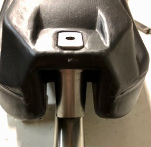
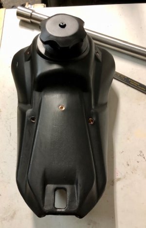
here's the tank
IMG_4535.jpg
designed for a 125cc pit bike, the inexpensive tank holds 1 gallon.
hopefully that will translate to about 40 or 50 miles of ride time before refueling
[the stock tank was 1.6 gallons- the stock CT90 was supposed to get somewhere in the neighborhood of 100 miles per gallon
i cannot substantiate that, i have never rode one that long.]

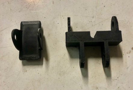
the brackets to attach the stiffener to the frame have been created in PLA plastic.
IMG_4513.jpg

i also designed and printed the standoffs for the fuel tank.

i'll manually reproduce the printed part on the lathe and milling machine as follows:

today i worked on the rear fuel tank standoff .
i made a 3d printed copy, but i found out my estimated length was too long
after finding the length that was going to work, i went to the task of creating a copy
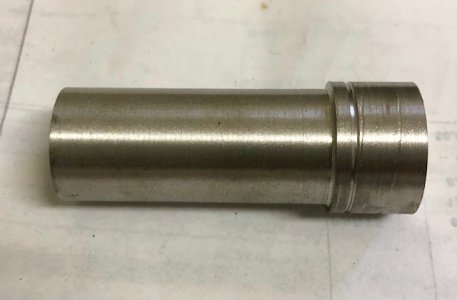
the first step was to turn a 35mm x 200mm piece of scrap 303, into a 28mm x 70mm piece of 303.
i further reduced a 50mm section to 25mm
IMG_4529.jpg

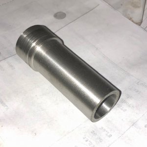
then bored the 25mm end to a wall thickness of .110"
IMG_4531.jpg

the standoff was then drilled to 17/64 , ready for a M8x1.25 tapping !

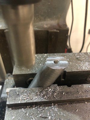
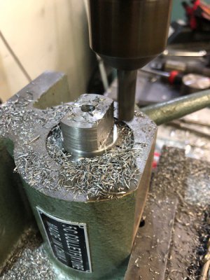
i put he standoff into a 25mm 5C collet and held it in a vertical fixture, in the vise of my Bridgeport
IMG_4532.jpg
i reduced the rod to a rectangle 15mm x 24mm
after hitting both marks, i remounted the standoff in the 1236 lathe and knocked off the corners off the 15x24 rectangle
to match the radii of the tank mounting bore better

i remounted the support in the vise, pinched with v-blocks to relieve the convex section of the standoff to be welded to the stiffening leg

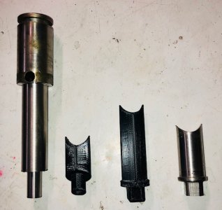
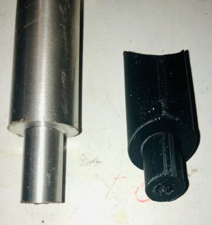
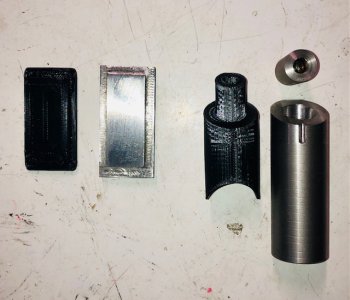
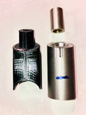
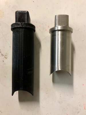
here is a picture of the standoff next to the 3d replicant
IMG_4533.jpg

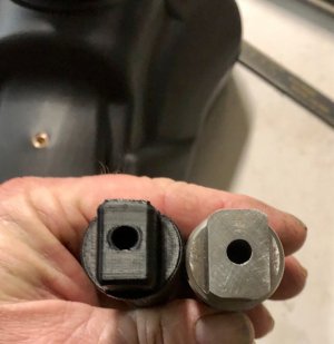
here is the fitted rectangular end, and the 3D printed concept that the standoff was modeled after
the metal copy fits the
IMG_4534.jpg

and the test fit
IMG_4536.jpg


in the next act,
i'll be tackling the front fuel tank standoff and welding it up!

Stay Tuned!!!
 
Last edited:
I understand that some of the Chinese engines will bolt right up to these. They are Honda clones, anyway.
 
Last edited by a moderator:
I understand that some of the Chinese engines will bolt right up to these. They are Honda cones, anyway.
Yes the frame pattern matches, but there is modification necessary to use the stock pegs.
DrATV sells a bracket ($20) that makes up the difference in offset.
the Lifan motors get good remarks, but are not as good as the honda engines in regards to longevity.
the lifan displacements are larger, but a lot of the QC leaves a lot to be desired
if you want to put an inexpensive motor in a dead bike to go have some fun, i'm not opposed to the notion

on this build, i'm going to be increasing the bore size by 15%.
i'll retain the reliability of honda cylinder, head and piston- just from a different source
soon to be revealed :grin:
 
Today on As The (motorcycle) Wheel Turns........

i managed to start making the front tank mount by modeling it in 3d for printing purposes
i have gotten used to the Tinkercad(TC) software.
i realize TC was designed not to challenge 1st graders nowadays,
but i have even (somehow :dunno:) overcame that hurdle to make some respectable parts :grin big:

the design started much like the rear standoff.
the front standoff has different interface to the tank as compared to the rear.
the design is basically a 25mm OD tube for most of the feature , diverging into a wedge, that will be turned from scrap stock
the wedge end end will be center drilled to 13mm to accept a custom stud, then 30° milled off to create the wedge.
i'll turn the basic stud length and diameter ,after turning of the 25mm diameter mark.
the other end will be milled to 12.5mm depth with a 1" end mill to create the weld interface with the support tube

here is the pictures up to now...


right is the completed front standoff, to the left is the nearly formed cadaver to carve the other support from

IMG_4589.jpg
IMG_4590.jpg

IMG_4591.jpg

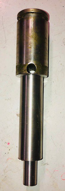
the cadaver is a reacclimated 303ish meat saw shaft
( i got a 300 pound stash of used meat saw shafts waiting to be repurposed)
i say 303ish because i do not know the exact composition.
it machines slightly differently than most 303 i have been exposed to , but not as unforgiving, work-hardening, and stringy as 304
it mig welds without evidence of porosity on Tri-Mix

i'll be knocking the nub off and thread the end of the stand off to accept the stud
i'll drill and tap the stud to accept the tank attachment bolt
i'll reinstall the stud after the 30°'s been whacked off the end
then return the set up to whack 30° off the stud, to keep the alignment plane of the stud/tank interface.

that machining has yet to be done, stay tuned!!!!!!
 
this is an update to other parts of the build going on simultaneously with the tank standoff...


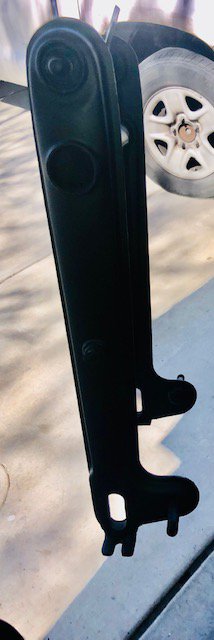
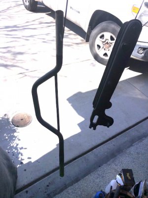
the swingarm and the bars have been sanded to 500 grit, primed, and painted flat black

IMG_4582.jpg

IMG_4583.jpg

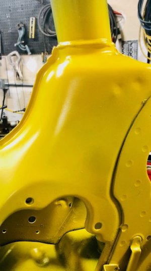
here is a test of the body paint

IMG_4588.jpg


Now for something completely different.....

i took a look at the rear rim wondering should i bail or should i fight ????

I chose to take up the gauntlet and do my best to breathe new life form old

here are the facts...
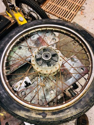
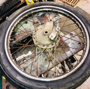
complete, original 1967 rear wheel (less the infamous double sprocket arrangement)
old, rusted, looks like shinola spread on white horse
the brake assembly is complete but needs help
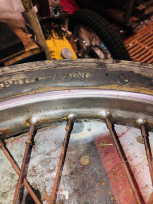
the tire , tube , and rim strip, all are considered beyond thought of reuse.

the photos...

before

IMG_4584.jpg IMG_4585.jpg

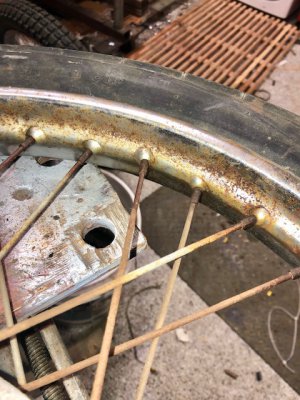
after about 30 minutes of work with phosphoric acid and a scotch brite pad,
i'm beginning to see chrome under the rust!!!


After picture...
from heavily freckled to barely noticeable in a few minutes

IMG_4587.jpg IMG_4586.jpg
i have not touched the spokes yet,

i'm leaning more to replacement of the spokes than restoration.
i have not laced up a CT90 wheel before, we'll see how that goes!

i'll crack open the rear brake and chronicle that too , as this thread jumps around :grin big:
 
I had a chance today to gain some ground on a couple stalled parts of the project.
the first stall was in making the standoff for the fuel tank as i left off in Post#15 above.

from a 303 stainless donor i was able to extract the general features i will be using to finish the standoff
i parted a 1-1/4" section of the donor shaft that i had already turned to 14mm
then parted off a 3" long section of previously turned 25mm
i put a 30° angle block in the vise of the BP and knocked off about 1/4" to get the desired 30° face

IMG_4601.jpg

after putting the 30° feature on, i needed a 14mm, 90° flat bottom relief in the 30° end
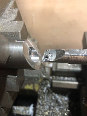
i mounted the work back in the 3j and used a boring bar to cut the, mostly interrupted, relief.
the plan worked like a charm with careful feed

IMG_4602.jpg

i stopped there for today on this part of the standoff.
for that, i'll need to measure and part final length,
bore the stub, and machine a concave feature into the end for welding, but that will be soon to come!

i was able to start making a go at the bracket that will be welded to the frame, that will attach the fuel tank support.
the bracket will be 2 parts.
i found a suitable piece of 1045 that was 25x65x8 in dimension
i used the BP to remove 3mm of material, to create a central step.
this step is a place keeper, it will be inserted into the hole in the frame, for centering purposes be fore welding.
to this step plate, a U shaped feature will soon be welded.
the U shaped feature will be where the tank support bar will terminate in a bolted connection.
all of this to come in the next act, but for now i leave you with a picture of the progress on these 2 items!

IMG_4603.jpg

as always, thanks for reading


More to come shortly !!!!
 
i was able to get some quality time in with the bike today...

i chucked up the body section of what is to become the front fuel tank standoff, and drilled it to 1/2" to a depth of 2-3/4"
then opened the hole to get .110" wall thickness

IMG_4613.jpg
now that the boring has been done, i can mill the concave feature into the body of the standoff.
i'll add a piece of 5/16-18 allthread as a stud to connect the threaded 14mm od bushing i created earlier
after assembly, i'll remount the assembly in the BP and relieve the top of the 14mm feature to 30°.
it will then be welded to the support tube, soon to be discussed......


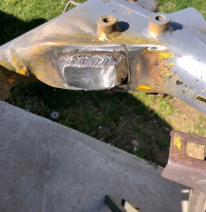
the second part of the quality time involved fitting and welding the front fuel tank support bracket base into the frame
although not my most glamourous works, i was able to take a hot pass with some 1/8" E6010

IMG_4612.jpg

i'll be constructing the bracket to weld to the base plate in the near future,
in the mean time i started spraying parts of the bike that won't be affected by a welding sequence

soon to come...
Rear Brakes
Rear Wheel Re- Lacing

Same Bat Channel!!!
 
Back
Top