-
Welcome back Guest! Did you know you can mentor other members here at H-M? If not, please check out our Relaunch of Hobby Machinist Mentoring Program!
You are using an out of date browser. It may not display this or other websites correctly.
You should upgrade or use an alternative browser.
You should upgrade or use an alternative browser.
New to me and some VFD help needed
- Thread starter 14617TKX
- Start date
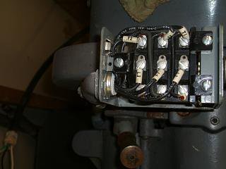
I have read that nothing should be between the VFD output and the motor. Part of me feels that the three phase output should go into the drum switch as L1 L2& L3 as labled so you can have stop foward and reverse.
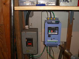
Single phase 230V into the top terminals is correct
The wires coming out of the VFD on the bottom are/should ( have no way to ascertain if three phase, just able to tell if 230 volts) be three phase
So I am going to connect VFD output to L1, L2 & L3 terminals on the switch after I set/check the settings per the instructions. May be a day or two till I get to it as another work week starts early and thirteen hour days doesn't leave time for much else till maybe Friday or Saturday.
- Joined
- Jan 22, 2011
- Messages
- 8,031
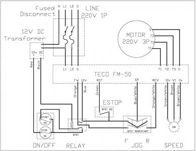
For reversing a 3 phase motor, you just swap any two legs on the supply. The VFD is fully capable of that, so you will not need the drum switch. Wire directly to the VFD.
Don't put anything between the VFD & motor. The motor hooks up to the bottom side of the VFD, input power hooks up to the top of the VFD. If the motor doesn't turn correct rotation, swap the two outside wires on the bottom of the VFD.
Or just use your programming to reverse it.
Using remote switches can be done & is explained in the programming manual.
Or just use your programming to reverse it.
Using remote switches can be done & is explained in the programming manual.
Last edited by a moderator:
- Joined
- Sep 22, 2010
- Messages
- 7,223
Attachments
Last edited by a moderator:
Well I'm going to try to find some time this week to crack the manual open again and try to develop a plan of attack for the upcoming weekend when I will try to hook up a switch for reversing the motor direction. Yall's help and words of advice are appreciated. Will let you know how it progresses.
Last edited by a moderator:
- Joined
- Jan 22, 2011
- Messages
- 8,031
You do understand that the VFD control handles forward/reverse switching, right? There is absolutely no reason to add a switch for that purpose. In fact, the sudden high current event that occurs if you happen to want to switch directions by using a drum type switch can and probably would ruin the VFD. They are dependent on information derived from the back EMF that you would definitely interfere with by putting any sort of switch between the motor and the VFD.
Everyone here has indicated that you shouldn't put anything between them, and yet you seem determined to do so. May I ask why? What is it that you hope to gain? Perhaps if we understood, we could offer some safer alternative.
Everyone here has indicated that you shouldn't put anything between them, and yet you seem determined to do so. May I ask why? What is it that you hope to gain? Perhaps if we understood, we could offer some safer alternative.
Last edited by a moderator:


