New shop! (was: Multiple buildings, ...)

Simple CAD sketch. Imagine the cylinder is a brush, free to spin, moves across the beam with the end truck. Because of friction, the cylinder will spin. Because the cylinder is at an angle, the bristles have some motion that is toward the flange edge. Since it is rotating, debris is much less likely to stick to the brush. Since this beam is about 11' up, I think a fairly soft bristle would be effective in remove the dust likely to find it's way up there, I don't foresee heavy debris, maybe a few chips but even that is unlikely.
View attachment 416394

Figure a bristle tip sticks to the beam for a small distance, over which distance the brush angle induces some deflection toward the beam edge. When the bristle tip releases, that deflection results in the bristle springing back in a direction toward the beam edge.

I familiar with the concept from wheel rakes for hay, but the same principle is used as a conveyor brush

In a crane application it would tend to sweep right in one direction of travel, and left in the other. A slotted mount for one side of the brush axle would allow it to pivot so that it would sweep off the same side regardless of travel direction.

Thanks for the explanation. If you like the angled, unpowered, slotted mount, rotating cylindrical brush concept, I'm 100% OK with your choice. It's your project and I'm sure that what ever you come up with, in the end, will suit your purpose.

I guess I'd have to test the concept to see how it would perform. I'm not hopeful.
I think the wheel rake is a vastly different and specialized apparatus. It doesn't help me understand the efficacy of unpowered cylindrical brushes. I'm also underwhelmed by the conveyor brush example. After all, a conveyor belt recirculates so gravity will remove debris. IMO, regarding "light cleaning", a conveyor brush can have a scrubbing effect on the surface of the belt which may dislodge adhered contamination allowing gravity to finish the cleaning.
 
Thanks for the explanation. If you like the angled, unpowered, slotted mount, rotating cylindrical brush concept, I'm 100% OK with your choice. It's your project and I'm sure that what ever you come up with, in the end, will suit your purpose.
I'm going to focus on getting the legs installed for now. I'm eating this elephant one bite at a time. The rest is ... somewhere down the road.
 
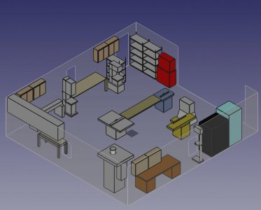
Playing in FreeCAD to create a model of the old shop which will be dedicated to woodworking. Actually wasn't that hard to create a 3-D model. But true to FreeCAD's quirks, the labeling tools don't like the model I created given the way I grouped things to make moving them around easy. There's probably a way to do this properly, but given that FreeCAD is a jumble of tools (called workbenches) that aren't well integrated, it didn't work with my model.

Shop looks so clean and open when you only show the major components. All the clutter just magically disappears! I still have my go-to lathe and mill in this shop, so this is just some planning for when all the machining gets moved to the new building. SOON!
woodshop2.jpg
 
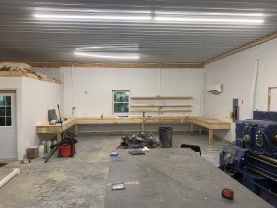
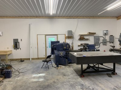
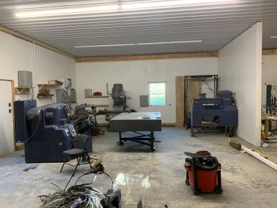
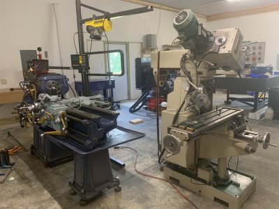
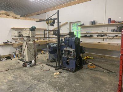
Shop is about ready to start moving the day-to-day machining tools in. Just finished up building the benches, still working on shelves. Basically I'll have shelves above the bench most of the way around. Pictures from left to right of the back part of the shop. The daily use mill and lathe will be set in the center of the U made by the benches.
IMG_4709.JPGIMG_4715.JPG
IMG_4714.JPG

It isn't completely clean, but moving stuff in will be a shuffle of moving stuff down to this shop, cleaning stuff out of here, and eventually getting a dumpster to clean up.
 
Looking good Randal.

Please explain the framing/panels on either side of the man door in the machine shop area.

It looks, to me, like the side panels may be intended to be removeable to create a large opening.

I don't remember that being discussed before. What's up there?
 
Looking good Randal.

Please explain the framing/panels on either side of the man door in the machine shop area.

It looks, to me, like the side panels may be intended to be removeable to create a large opening.

I don't remember that being discussed before. What's up there?
Just the way the doors are framed up.
 
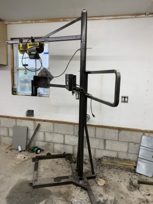
Moved the daily use mill and the lathe from the old shop, which is officially now the wood shop, to the machine shop. The mill, at about 2000 lbs factory spec, was fairly easy. The lathe, at somewhere around 3500 lbs, was more of a challenge. I had the lathe headstock sitting on a base that mounted the DRO, VFD controls, and a jib crane. This made a stable base for the jib crane, which is meant for a couple hundred pounds at most, usually lifting chucks on and off. It also raised the whole lathe up about 2".
IMG_4723.JPG
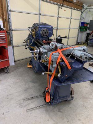
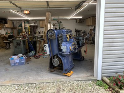
Got the lathe on skates and a shop made set of pallet jack wheels, and rolled it to the front door (it was, of course, in the back corner).
IMG_4724.JPG
I have to say, I think I'm going to throw these amazon skates out. They are just not what you want to use. They are big and impressive and have some ridiculously overrated capacity (6 tons?). But in addition to the previously mentioned issues with the urethane rollers, they sit way too high. They need about 6" of height to get under something. If the base of your mill/lathe is 24" wide, then 6" of height is a fair amount of tilt. Probably more than you want to lift one side, so I found myself lifting one side part way, blocking it on wood scraps, then lifting the other all the way to get a skate underneath, then back to the first side. Tedious, but not unmanageable. But if you have skates on two sides 24" apart and one comes out while you are rolling it, that 6" drop is much worse than a 3" drop. Yeah, that happened (blush). Fortunately other than a divot in the concrete, no harm done if you don't count sudden heart thudding.

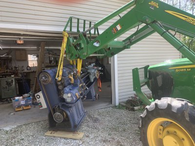
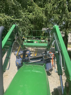
Anyway, the challenge is the garage door on the now wood shop is 7' high. That is the opening height, knock about 6" usable height off of there for the garage door not quite opening all the way. That leaves little clearance over the top of the lathe for getting something in to lift with. My tractor loader/forklift can lift just under 3000 lbs on a pallet, a bit more if you get the lift point all the way back to the forklift frame. I removed the tailstock and chuck to take some weight off, then rolled the lathe all the way to the door and just managed to get the loader in enough to lift the headstock with the tailstock still on rollers, and pull the lathe out from under the doorway. Then I could get the loader frame over the bed of the lathe to hoist with rigging straps. The strap on the motor end is really for balance, it was about 50lbs heavy on that end with the main lift point on the bed cross webbing nearest the headstock. The orange ratchet strap is just to hold the wheels on to the tailstock end when the lathe was lifted.
IMG_4726.JPG
IMG_4728.JPG

The tractor is a 16 gear F/R, this is probably the first time I've felt like idling in lowest gear was still too fast. Pictures didn't catch it but I had a 7' drag blade on the back of the tractor as a bit of a counterweight. And I added air to the front tires.
IMG_4732.JPG


So at this point, all of the machines are in the new shop! Quite a bit of work to do yet in terms of hooking them back up, I have to run the in floor electrical through the conduit, finish up the shelving, and then get everything organized. One thing about the layout I fixed: these older lathes are really meant to be cleaned out from the back side, unlike the boxed in modern lathes. That means you need clearance around the back to get in and clean up, in the old shop I had the lathe pretty much up against a wall. Obviously no longer so in this shop. I'll eventually put the 10EE back to back with this lathe, with about 30" between them to get in and clean.

IMG_4733.JPGIMG_4734.JPG

I'm off to for cross country travels this coming weekend for my bi-annual cancer followup. Which is also a chance to see my family, including my father who was just in the hospital for more heart issues. I've more or less made my goal of having this shop "commissioned" by that time. Time to break out an adult beverage and declare victory. I'm declaring this shop done and ready for use. Well, at least usable and almost done. I still need to build the bridge crane (you can see the white supports in some of the pictures). But I can start using it now. Guess I'll close out this thread on that note.
 
Last edited:
yea, those skates look high. Can you machine them down on the sides then redrill and put new axles and use bearings for wheels.
Also maybe remove the pad on top, and put a rubber flat pad on top... leave a hole in the center for the leveling screw, it should keep it from bailing on you... it should just drag it along..

hope your checkup is good.
 
So at this point, all of the machines are in the new shop! Quite a bit of work to do yet in terms of hooking them back up, I have to run the in floor electrical through the conduit, finish up the shelving, and then get everything organized. One thing about the layout I fixed: these older lathes are really meant to be cleaned out from the back side, unlike the boxed in modern lathes. That means you need clearance around the back to get in and clean up, in the old shop I had the lathe pretty much up against a wall. Obviously no longer so in this shop. I'll eventually put the 10EE back to back with this lathe, with about 30" between them to get in and clean.


I'm off to for cross country travels this coming weekend for my bi-annual cancer followup. Which is also a chance to see my family, including my father who was just in the hospital for more heart issues. I've more or less made my goal of having this shop "commissioned" by that time. Time to break out an adult beverage and declare victory. I'm declaring this shop done and ready for use. Well, at least usable and almost done. I still need to build the bridge crane (you can see the white supports in some of the pictures). But I can start using it now. Guess I'll close out this thread on that note.
Hey Randal,

Thanks for taking us along for the ride! I know it's a pain to worry about taking pictures while you've got some heavy iron swinging in the breeze! Looking forward to seeing your future projects!

Bruce
 
Designing the crane in FreeCad. Initial issue is to get the layout and length for the legs. Then I can fab the legs and drill the anchors. Upper structure will be installed later. This design will get some additional bracing. I'll connect the ends of the side rails together, and put in some diagonal bracing between the legs.

Crane spans 22' for the bridge, and about 38' long side rails. Capacity will be 1 ton. Higher capacity would be more expensive, and more importantly, heavier. I'm going for an unmotorized design.
...
These end trucks are 24" long as shown. Going to redo them to be 36" long. Longer means not quite getting as close to the end walls, but will reduce issues with the bridge beam racking off square. There will be follower wheels to keep them square on the rails, just didn't add those, or the bushings and axle bolts, etc, into the CAD.
I'm replying to this thread, since you pointed me here.

Somewhat different design, but it seems like you have a lot of the same concerns I've been having! Wiping the rails, keeping it clocked, etc.

Side rail length is 40', with 24' span. Target here is a 2 Ton capacity, and this is a 'low overhead' design. The bridge will be made with two beams, with a 'truck' to span them, ~24" apart. The rails have been up since Oct 2021, but the bridge isn't completed yet. Need to get that steel up off the floor and out of the way soon!

Keeping the bridge clocked/parallel was a big a concern here also. The decision here was to narrow the trucks a little, and run a small roller chain the length of both rails on top of the rails. That chain loops around a sprocket on the bridge at each end, which is connected via square 'driveshaft'. This ensures both ends are always clocked against each other. The plan is to drive the driveshaft with a hand chain wheel. That mechanism will be movable up and down the bridge. Yeah, really over complicated but it's a once in a lifetime build, so why not...

How did you size the bridge rail? What sort of safety factor did you look at?

Dan
 
Back
Top