Needing more than a spark test?

Very likely, the route in is by conducted interference carried in on the 0V end of the powering arrangements. If the rest of the kit is reasonably electric field screened, then there remains the possibility of low frequency ingress by magnetic coupling, but that would be 60Hz from house wiring and appliance cables. Switcher racket from LED lamp mains step-down electronics has higher frequency blips, and finds it very easy to contaminate the house mains, the wires being quite effective transmission lines. I guess it might be time to bring out the common mode chokes and suppression measures.

It is actually possible to prevent such noise riding in on the conductors. Provided the kit has reasonable electric field screening, you can expect to be able to eliminate the switcher waveform contamination, and let the lamps keep making a racket.

Even getting a scope to confirm the noise on the trace is real can be a challenge. I have found I often cannot just clip the ground of the probe to a 0V, and the common way of allowing the circuit 0V to find it's way onto frame metal would likely defeat attempts to get the signal clean. In my stuff, the usual effect of such grounding does, to a reasonable degree, reduce the coupled trace noise wobbles to a certain low(ish) level), which then resists attempts to clean it further until the circuity is isolated from the frame. Sometimes you can see "PSU switcher noise", and discover it is just a measurement artifact that goes away when dual differential probes are used.

TFT display, being so intimately connected to measurement circuits, might perhaps need to be separately cleaned up. I think I would be unhappy with as much as as 10mV, but I do accept that the 500uV to 1mV level is a darn hard thing to achieve.
Long ago I put a commercial line filter in a box, along with a power outlet connected to the output side, to filter out line noise. I dug it out and tried it, didn't observe much of a change. But see below.

Turning the scope probe into an antenna loop (by connecting the ground clip to the probe) revealed lots of EMI coming from my scope. It's worse near the back, probably from the scope's switching power supply. Evil things they can be. It seems likely that the scope is a major source of the noise I'm seeing -- it was on the filtered side of my little line filter setup.

I'll have to try my little battery-powered DSO. It could still contribute some noise from its TFT but hopefully no switching PSU is in it.
 
One thing I tried that was a bit more revealing w/regard to the actual ripple coming out of my PSU was to trigger the scope using one of the switching signals on the inverter board. I still had a bunch of other noise coming in from elsewhere so I put the scope into its averaging mode. Then I started seeing ripple I could start to believe in. It's about 7mV peak to peak. Thing is, the time frame is about 2us for that much delta-V. Going into how much current has to flow into the filter capacitors to produce that voltage change in 2 microseconds yields an absurd amount of current. The only current draw is the 100 megohm voltage divider used in my feedback loop. So I think I'm seeing the circuit ground(s) bouncing around, probably due to switching currents in the inverter.
 
One thing I tried that was a bit more revealing w/regard to the actual ripple coming out of my PSU was to trigger the scope using one of the switching signals on the inverter board. I still had a bunch of other noise coming in from elsewhere so I put the scope into its averaging mode. Then I started seeing ripple I could start to believe in. It's about 7mV peak to peak. Thing is, the time frame is about 2us for that much delta-V. Going into how much current has to flow into the filter capacitors to produce that voltage change in 2 microseconds yields an absurd amount of current. The only current draw is the 100 megohm voltage divider used in my feedback loop. So I think I'm seeing the circuit ground(s) bouncing around, probably due to switching currents in the inverter.
I think you have it right!

Keep in mind that some SMPSUs actually need some load current beyond what a 100 megohm load provides, just to get their control loop into operation. The energy storage capacitor / low pass way is not effective against higher frequency bumps, and by basic nature, if it has to supply currents, it will inevitably make ripple. As you say, getting at the switcher ripple by using capacitors would involve high currents, even if for very short times.

The more absolute way is to use a post regulator linear regulator that has a very high bandwidth, so fast that it can follow the ripple transients, and regulate them away. The problem then becomes making a very clean reference.

I have also been disappointed by some commercial mains line filters, until the day when I was providing generator support to some radio enthusiasts field day, when I was shown the one that also choked the ground line. Those guys could make the contribution from power line interference become hard to detect, even on a field with full blast HF transmitters coupling directly into them.

Extra regulator stages may not be conveniently practical, and is a different thing to deal with than power line conducted rubbish from LED supplies designed down to a price. The rules for these might be different in USA than we have in Europe. Regardless, once you know where the currents are, and how they interfere, then you can definitely stop them.

It gets desperate if we have to reach to more complicated and expensive low ripple supplies, like a highly developed Ćuk converter. Also, the effective way to stop circuit grounds "bouncing things around" is to deny these routes the currents. There is always some inductive impedance in the ground connection, and the idea that "ground" is some kind of massive sink that can stay at 0V no matter what we try to dump into it is just wrong. For me, the switcher currents usually involved motors, in one project, a pair at more than 70kW each. Stopping noise had to be the most frustrating aspect among all of it!
 
Last edited:
CCFL inverters don't seem to have a feedback loop. More-sophisticated ones can detect an open condition, probably by looking for ringing on the un-loaded secondary. I had to defeat that feature in order to keep the inverter running -- once the capacitor on the other side of the HV diode charged up, the inverter would shut itself down!

I'm thinking about using an optocoupler to isolate the inverter from the linear control circuitry. That would remove any possible ground bounce, but it would require a separate power supply to run the inverter. I have a spare (linear) 12V supply I can use to test the idea....
Yes yes!
At the very least, you eliminate the ground sink route. Anything left over, if at all significant, can be hit by other measures. :)
 
This is just to let you folks know that I am still hanging in there.
In between the various other things that will definitely be affecting my life, I have got as far as getting into knots with a horror called "DRC check".
The necessary household stuff is not going to complete, and be out of the way just because I want to play with electronics and radioactive stuff, but I am making time to try and press on

My KiCad user library setup evaporated when I did the computer recovery. I do have the old library content backed up, but as it happens, the actual design was unharmed because KiCad stores a copy of everything one used kept within the project file set. Everything is going much slower than I had hoped. I am in danger of Raspberry Pi production availability catching up with me again. :)
I know what you mean. Millions of things to do, lots of projects just needing to be done, some of them yesterday.

Haven't progressed on my KiCAD layout either. I still am at V6, and am dreading a "forced" upgrade. So far, been able to prevent it. With a previous simpler design, DRC wasn't too bad, just had to plod through them all. As I have added stuff to my design, I did do DRC, and was able to clean up most of it. I still have a few more power planes to complete though, and they are the harder ones.
 
This is just to let you folks know that I am still hanging in there.
In between the various other things that will definitely be affecting my life, I have got as far as getting into knots with a horror called "DRC check".
The necessary household stuff is not going to complete, and be out of the way just because I want to play with electronics and radioactive stuff, but I am making time to try and press on

My KiCad user library setup evaporated when I did the computer recovery. I do have the old library content backed up, but as it happens, the actual design was unharmed because KiCad stores a copy of everything one used kept within the project file set. Everything is going much slower than I had hoped. I am in danger of Raspberry Pi production availability catching up with me again. :)
Summer garden stuff is taking the lion's share of my time so my progress has slowed, too. Our cool spring turned warm very quickly and we are now working hard to get everything planted/sown out. Looking forward to the home-grown veggies, that's for sure!

Despite the summer things going on, I have acquireed the parts I need to build and test the HV supply's opto-isolator control loop, and have done a few simulations for a sanity check. Learned a few things, like accounting for the current transfer ratio. You have to make sure you have enough "drive" capability for the LEDs or your control loop doesn't work very well! I'm planning on using a dual-channel opto-isolator and using one transistor in the feedback loop, in the hopes that this will linearize the response of the LED/transistor that are actually controlling my CCFL board. I don't expect great channel-channel matching since the LEDs (and presumably the phototransistors) in the packages are discretes, but it's probably going to be better than noting. The odds are good that the LEDs are relatively well matched, since they probably came from the same manufacturing lot, and perhaps from the same region of the wafer; and the same goes for the transistors. But that's not guaranteed!

I've run into DRC problems when using EasyEDA, too. One of its quirks is that it doesn't automatically generate clearances around vias when they penetrate areas with copper pour (like the power and ground planes). You have to periodically "re-draw" those layers or you get DRC errors all over the place.

Presumably other types of DRC errors would be addressed if using their auto-router but the few times I tried using it were not pretty. I haven't tried running the auto-router on a fully laid-out PCB that has DRC errors yet.

Quite a few years ago my wife worked for a company that designed custom IC's for reformatting video streams. They handed their design to a fab house, who simply ran the design through their auto-router. The resulting parts sorta, kinda worked but tended to crash at higher clock rates or when operated close to their temperature/supply margins. Examination of the layout revealed some pretty terrible spaghetti traces the auto-router created, leading to timing margin problems. Apparently my wife's company should have done a better job of specifying critical signal lines for minimum length, so they paid the price for their ignorance regarding the foundry's layout practices.
 
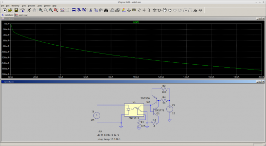
It's been raining the last two days so I had some time to play with my opto-isolator based HV controller:

Opto-iso HV Control.png

The design is a sorta-kinda current mirror scheme with current gain.

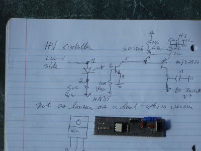
And here's my hand-drawn sketch along with the hand-wired version I will stitch into my CFL-based PSU:Controller.JPG
My hand-wired board is about 2 inches long, built on a scrap of my slowly-dwindling supply of vector board. I had most of the other components on hand. The only exceptions were the power resistor and power transistor. I have a partial roll of wire wrap wire I use for point-to-point connections. Also slowly dwindling.

The 4N35 opto-isolator is specified to have a "typical"1:1 transfer ratio. It's the white-colored package on the board.

I haven't tried this thing yet, I need to modify my inverter circuit to completely isolate them. I think have everything I need in order to test the scheme. But the rains are supposed to come to an end so it's hard to predict when I will have any results to share.
 
XRF used to sort "clean" aluminium - apparently.
I came across a video about recycling aluminium, and I admit I did not get way into the detail, but I am sure this is a direct application of XRF.

We see a (huge) set of 160 keV sources used to blast X-rays onto cut up chips of recycled aluminium on a special conveyor which uses specially controlled air blasts to knock the detected alloys into their sorting receptacles. Given the low, almost transparent nature of aluminium to X-Rays, I guess the machine might be detecting the contaminating alloy elements instead. Of course, it's way out of my league, but interesting.
The first 4 minutes relates to XRF

 
Last edited:
Back
Top