Need VFD education

70sum

Registered
Registered
Joined
Apr 13, 2023
Messages
15
I have temporarily hooked up an AT series VFD to the Enco lathe I recently purchased to check the motor. I now want to install it permanently. I want to use the clutch lever for the control of the motor forward and reverse and stopped positions. The control lever has 2 normally open switches on it. One forward and one reverse. It looks to me that I just have to use X5 for reverse and X4 for forward. To stop in neutral, what would I use? Add another switch? Would the motor stop once the N/O switch opens? Is the start circuit a latching circuit from the button on the VFD? Other questions I have are: Is a magnetic contactor needed between the VFD and the motor? I now have temporarily installed a 220 off on switch going to a pilot light then a 220 circuit breaker and then to the VFD. Would fuses be better than the circuit breaker? I need a great deal of education on wiring this VFD. I also purchased a milling machine and will need help with that also.

Thanks in advance for any info.
 
First, you don't want any switching or contactor between the VFD and motor. Wire direct.
You should be able to use the two clutch lever switches to do forward, reverse and stop. Check the VFD manual.
It should show a connection diagram and some recommended settings- if it seems too confusing see if you can
post a link to the manual here so we can take a look at it.
Not sure if you need both a switch and a second breaker on VFD input power side- doesn't hurt tho
The VFD draws little power when the motor is stopped, it's ok to leave the VFD on
Living in an area that has frequent lightning would be the exception I suppose
-Mark
 
Last edited:
I have no idea what the AT series VFD is, do you have a make and model?

VFD's digital inputs control the VFD operation, these vary based on the VFD model/brand. The VFD output is directly wired to the motor, the VFD digital outputs control the operational conditions/commands. The digital inputs typically operate al low DC voltages, and a few mA.

Two wire control is used where you have two NO switches, one for forward, one for reverse, one the switch is closed and maintained that direction is active. So requires a maintained closure to stay active. Down side is that it requires a maintained closed switch and can be a safety issue if the VFD operation is interrupted, and then reinitiated with an active run command.

Three wire control uses momentary buttons for the RUN (NO) and STOP (NC), reverse usually requires a sustained ON input to remain active, although some VFD's may have a separate momentary (NO) for that direction. There is also certain logic sequence as to the hierarchy of commands, these are indicated in the manual.

Relay/solid state control systems are sometimes used to switch the VFD digital inputs, depends on the what the system design requires. So one might use a latching relay that requires the lathe to be in the stop position to latch, if there is a fault it drops out, also some VFD's have parameters that if you reset the VFD due to a run fault it will not restart operation if there is an active run command on reset.
 
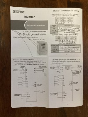
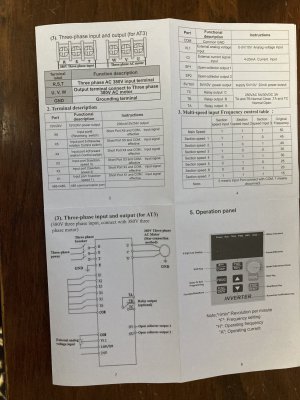
Thanks guys. The VFD is an AT Simple general series XCFDP VFD. There is no manual with it or one I can find online. Cheap Chinese VFD. For the direction switching the terminal description reads X5 input port 5 reverse rotation control switch. Instructions say short port x5 and com, input signal effective. I assume that means the 2 wires from the N/O switch,one to the common terminal and one to X5. Forward rotation is the same except use X4 and common for that direction. I am assuming the X terminals are low voltage. The X terminals also listed as X6 input port reversing switch. Any idea what that terminal is for?
thanks again for any info

I realize that some parameters will need to change to make the N/O switches work if I wire them up right.
thanks again
 
Last edited:
First piece of advice- never buy a VFD without some type of manual either online or printed- It's a major limitation not to have one
What information do you have and where did you purchase the unit?
 
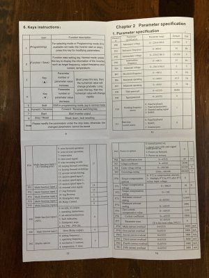
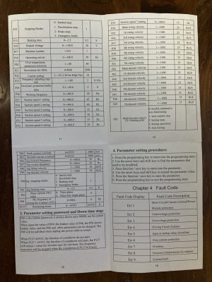
The information that came with the VFD is a 2 sided foldout with basic wiring for 220 single phase input to 3 phase output. Terminal description are listed for ports, 15/24 volt, X1 thru X6 and 485 com port, external analog volt input, external current signal input, open collector output 1 and 2, 5/10 volt output, relay output to 3 relays. The flip side is parameter specifications and error messages. I had thought since the VFD was converting to 3 phase the wiring would be straight forward. The motor is as you know, the controls would seem to me to be straight forward also since I just want the clutch lever to start and stop the lathe. This shows how little I know about a VFD. Purchased off Amazon. For the amount of time I will be using it I figured an inexpensive VFD would be fine.
Again thanks for educating meIMG_1521.JPGIMG_1522.JPGIMG_1523.JPGIMG_1524.JPG
 
Last edited:
OK so you do have a manual, or information sheet I guess is more accurate.
It looks like X4 and X5 and the COM would be connected to your forward and reverse switches.
Not sure about some of the settings- I need to study it for a bit. These things can take a while to sort out,
so put on a pot of coffee and your reading glasses
-M
 
Question: Have you run the unit yet at all? Get it running first and then connect the switches is what I would do
Most of the defaults you can leave alone- I'm going to start a list of the settings you will need to change:

Page 10:
P01= 60 hz
P03= 30 hz
P11= 0 for local control, 2 when external switches connected

Page 11:
P18= 60 hz

Page 12: no change
Page 13: no change
Page 14: no change
Page 15: no change

I probably missed something, but start out with these settings and report back
 
Last edited:
I've got this same VFD running my mill.
Wire the switches to the Xn terminals so that when the switch closes it connects the terminal to ground. The function stated for each terminal is the default function. You can then program the P5n settings to change the function of each terminal to what you want it to do when it gets tied to ground.
You have to read that "manual" about ten or twelve times before what should really be a simple thing is clear.
 
Back
Top