[Newbie] Need Help With Soldered Tinplate Model Ship Project

Guitylerham

Registered
Registered
Joined
Sep 7, 2015
Messages
16
Hey everyone,

I am in the beginning of a new project: a 1/144th scale RC model of the Titanic. The catch is that I've built a wooden former over which I'll solder 1/2"x 2-1/2" 0.010" tinplated steel pieces to recreate the look of the riveted 1" thick steel plates on the original. Once, completed, I'll remove the wooden former leaving an empty shell.

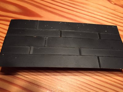
I have soldered a test sample of brass pieces to see if it was possible and was happy with the results. I think the tinplate will also be fairly straight forward as far as soldering but I'm having a little trouble planning some aspects.
IMG_2516.JPG

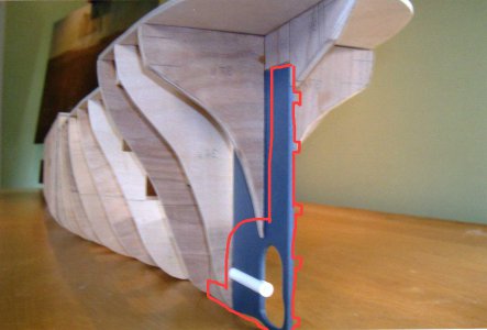
The stern section will have a frame constructed of brass that the aftmost hull plates will terminate at and anchor to. Here's a picture of what I will be attempting. The red outline is what the frame will look like underneath the hull plates, inside the hull. My frame will be of either 1/8th or 3/16th 360 brass cut and filed to shape.

Titanic_props.jpg

Here's an example of someone else's model with the stern frame made from blue plastic much like my brass frame will be constructed. My propeller shaft tube will be brass and soldered to the frame inside a slot.
OWSMvBP.jpg

I'm learning about various ways to solder and the solder wire involved and don't know what I should be looking for. Because this brass frame is so thick and the hull plates so thin, can I get away with standard 60/40 and a big iron as long as I pre-tin both surfaces? Should a micro torch be used instead? Will I experience previous joints coming undone as I try to solder successive layers of plates as I move upwards on the frame towards the top?

Various solder melting temperatures have me perplexed! I want to buy perhaps three temps of solder. I'll use the highest temp solder on maybe the stern frame-to-hull plating joints (or should I use the lowest temp for that?), then use the middle temp solder for the majority of the rest of the hull plate-to-plate joints, and then the lowest temp for whatever detail will be added on top of the other mid-temp joined parts. My question is what would you experienced solderers recommend be my three temps of solder? "Tix" brand at 275F, 60/40 at 370F, and some other silver solder at 400F+?

I know a lot of this will come with practice but right now I need to know what I should order. I've read that acid flux should be used on brass, but what about it corroding the steel plates? I'd really appreciate any direction from more knowledgeable builders. This ship will be built in phases. First phase is the hull just up to the superstructure. I'm sure I'll have to adjust my plan once I start building boxes with corners and windows/doors, etc. but for now my goal is the hull plating.

Thanks for your consideration.
-Tyler
 
Hi Tyler,

I have never attempted something like that, and can offer no real advice for you but wanted to say:
1) Welcome to the site! and
2) That sounds like a very involved project. Sounds like you have done (and are currently are doing !) a bunch of research. Please keep posting! I'd really like to understand more and see the progress! Thanks.

You are correct that practice will be key.
I am sure you will get some knowledgeable answers very shortly.

Good Luck!
-brino
 
Tyler,
Jewelers use silver solders with a whole range of melting points when they make up complex pieces. They start with the highest melting point solder and work their way down in melting points as the add more pieces. They do this so that as they continue to solder new pieces, they won't disturb the previously soldered work. Tin lead solders come in a variety of different alloys: 50-50 (auto body solder), melt point 220C, and 60-40, melt point 188C being two commonly available. 63-37 or eutectic solder has the lowest melting point (183C) of the straight tin-lead solders. When you get into other alloys, there is a whole range of melting point temperatures. If you Google solder melting points you should find all kinds of info.

For what you are doing though, you may be able to get by with putting a dampened cloth on your previous work. Iron and steel can be difficult to solder. A good flux and freshly cleaned parts are essential. Tom has it right with the acid flux. I would check with an auto body supply shop about the flux they recommend. Plan on brushing it on separately rather than using a flux cored solder. Flux the parts before heating.

I have used a 200 watt soldering iron. It has a 5/8" tip for good thermal conductivity to the work. I would also have some means of controlling the temperature. Left on its own, the tip will glow red. A Variac transformer or a light dimmer should be able to control the temperature well.

It sounds like a fun project. Good luck with it!

Bob
 
So perhaps I'll just stick with 60/40 for now and see if I can reliably attach the thin tinplated hull plating to the 3/16" brass frame. I'll see if I can minimize heat spreading to previous joints with wet paper towels and heat sinks. It is indeed a complicated and crazy project but I am very excited to jump in. Excited and also nervous to start. Lot's of plates...

And thank you for the welcoming and all your responses so quickly! I appreciate what you all have suggested.
 
Once again, my two cents. I've done stuff like this a lot for radio chassis compartments and the like. I'll qualify this by admitting to a bias for using rosin core electronic solder wherever possible. Not only because it's what I'm most familiar with but frankly the rosin and 60/40 melting points make for clean quick work with a reasonable amount of heat. But in this case, you'll want to use as thin as possible solder, and I don't think you'll find 0.015" solder in acid core. Here's my reasoning. You don't need large flows of solder between plates, heavy solder will end up being too much volume by the time you get it flowing and move down a seam.

With the thin solder you can lay a tiny piece under a plate corner and heat it with the iron from outside. When the solder melts it will clean, wet and transfer the heat needed to the plate/frame underneath. You'll know when the flow has wetted between both pieces. Remove the iron, but continue holding the pieces together with some tool (pin, screwdriver, chop stick... your choice) until the joint cools. This should be quick since this method will impart the least heat to the work.

Repeat the process as required to tack the joint in position at the other end, or places in between, as needed to get the parts aligned as you like.

When done tacking you're ready to fill the entire joint. If you can do this from the back side it would be more forgiving but can be done on the show side with practice as follows. Using as small a tip as possible, maybe 1/16", lay a piece of solder along the seam. Touch the tip to the seam and push toward the
solder. Once it flows, continue pushing to the tip along the seam keep the tip wetted. It's a lot like caulking a bathtub where you push the bead ahead of the caulking nozzle. At the right speed you should have the solder solidifying no more than a 1/4" behind the tip as you move along.


You can "repaint" the seams as needed if you don't like a few.

Items you'll need/want:
IRONS:
A pencil type iron of about 70-100Watts. It should definitely be temperature controlled. You don't need fancy digital but it doesn't hurt. I use a Weller WCTPN type iron for work like this and a Hakko for more delicate stuff. The Weller use magnetic tips that regulate temperature depending on the tip selected. A little crude by todays standards but may be available on ebay for the right price. You shouldn't need to spend more than $100 for this.

A gun type iron like a Weller or Unger 200 watt.

Tips for the pencil iron 1/'16", 3/32" and 1/4" (700 and 800 degrees if buying WCTPN tips).

Flux: Xinc Chloride or Rosin type fluxes. You can buy water soluble types now but I don't recommend them. The oil based stuff works fine, cleans up easy and won't eat through your plating in years to come. Denatured alcohol followed by a decent degreasing solvent will leave a paintable clean surface.

Sponge to clean your tip just before each use. Ammonia (clear, NOT "sudsy") for the sponge. [They also make Sal Ammoniac blocks for this but again, not a good application here.]

Alligator clips, or way better, small hemostats (except they're longer, stronger and heavier, which isn't always better.)

A steady hand, a brave heart and an adventurous soul and you're good to go.

I have some ideas on how you might make rivets with the solder but I think you'll devine that one on your own.

If I think of anything else I'll re-post... and look forward to seeing your progress. From the look of your test piece I think you have this soldering part licked. I suspect the hardest part, as for any lapped hull, might be the fairing of the strakes as you try to twist around the compound curves. You may find yourself making a little tiny English Wheel or Planishing Hammer to get the shapes needed. :)

Mark
 
Last edited:
Once again, my two cents. I've done stuff like this a lot for radio chassis compartments and the like. I'll qualify this by admitting to a bias for using rosin core electronic solder wherever possible. Not only because it's what I'm most familiar with but frankly the rosin and 60/40 melting points make for clean quick work with a reasonable amount of heat. But in this case, you'll want to use as thin as possible solder, and I don't think you'll find 0.015" solder in acid core. Here's my reasoning. You don't need large flows of solder between plates, heavy solder will end up being too much volume by the time you get it flowing and move down a seam.

With the thin solder you can lay a tiny piece under a plate corner and heat it with the iron from outside. When the solder melts it will clean, wet and transfer the heat needed to the plate/frame underneath. You'll know when the flow has wetted between both pieces. Remove the iron, but continue holding the pieces together with some tool (pin, screwdriver, chop stick... your choice) until the joint cools. This should be quick since this method will impart the least heat to the work.

Repeat the process as required to tack the joint in position at the other end, or places in between, as needed to get the parts aligned as you like.

When done tacking you're ready to fill the entire joint. If you can do this from the back side it would be more forgiving but can be done on the show side with practice as follows. Using as small a tip as possible, maybe 1/16", lay a piece of solder along the seam. Touch the tip to the seam and push toward the
solder. Once it flows, continue pushing to the tip along the seam keep the tip wetted. It's a lot like caulking a bathtub where you push the bead ahead of the caulking nozzle. At the right speed you should have the solder solidifying no more than a 1/4" behind the tip as you move along.


You can "repaint" the seams as needed if you don't like a few.

Items you'll need/want:
IRONS:
A pencil type iron of about 70-100Watts. It should definitely be temperature controlled. You don't need fancy digital but it doesn't hurt. I use a Weller WCTPN type iron for work like this and a Hakko for more delicate stuff. The Weller use magnetic tips that regulate temperature depending on the tip selected. A little crude by todays standards but may be available on ebay for the right price. You shouldn't need to spend more than $100 for this.

A gun type iron like a Weller or Unger 200 watt.

Tips for the pencil iron 1/'16", 3/32" and 1/4" (700 and 800 degrees if buying WCTPN tips).

Flux: Xinc Chloride or Rosin type fluxes. You can buy water soluble types now but I don't recommend them. The oil based stuff works fine, cleans up easy and won't eat through your plating in years to come. Denatured alcohol followed by a decent degreasing solvent will leave a paintable clean surface.

Sponge to clean your tip just before each use. Ammonia (clear, NOT "sudsy") for the sponge. [They also make Sal Ammoniac blocks for this but again, not a good application here.]

Alligator clips, or way better, small hemostats (except they're longer, stronger and heavier, which isn't always better.)

A steady hand, a brave heart and an adventurous soul and you're good to go.

I have some ideas on how you might make rivets with the solder but I think you'll devine that one on your own.

If I think of anything else I'll re-post... and look forward to seeing your progress. From the look of your test piece I think you have this soldering part licked. I suspect the hardest part, as for any lapped hull, might be the fairing of the strakes as you try to twist around the compound curves. You may find yourself making a little tiny English Wheel or Planishing Hammer to get the shapes needed. :)

Mark

Thanks so much for the knowledge. I will be returning to this page many times to cement the ideas in my head.

In the beginning stages, I should be able to lift the project off the wooden former to be able to solder from the inside if necessary. It's even doable later on but as the hull takes shape, it'll be more difficult to reach the tight ends of the stern and bow. Once completed, I'll likely add a bunch of frames to the inside of the hull shell.

As far as rivets go, I've seen guys make photo-etched brass sheets that have the rivets etched. At this scale, the rivets would be so small that applying them individually with solder or any other means would be so much work. Fortunately, the only rivet details would be only three or so rows of plating along the sheet line where the hull meets the superstructure. These rivets were left raised while all the other rivets below were flush and basically invisible. I assume I'll just leave the rivet detail out of this project since I'm not sure I want to develop the artwork and process for photo-etching a bunch of plates. Not to mention all the portholes I'll be drilling and filling! I've certainly made this a challenging project but somehow that motivates me.

I think you're right regarding some of the compound curves and the overlapping of strakes. It will certainly be difficult and I haven't even really considered how I'll make those shapes yet. I'll look into an English wheel and Planishing hammer to see if that's feasible. Can you imagine the work involved forming an inch-thick plate of steel 6' x 30'? Templating each plate, drilling each hole, and setting each of the millions of rivets so they form a watertight seal at the seams? Most of the equipment was steam or hydraulically driven, horse-drawn, and sometimes electrically powered. I've got it easy!
 
My idea for the rivets was to tin the metal and then go over the cooled surface with the tip of the iron making little raised solder bumps. Too much heat/time and they'll flatten out, too quick and they'll be pointy like Hershey kisses (which I'd soften with a little sanding or Dremel wire brush for uniformity). Just an idea... wear a mask for that!

And I often marvel at what was accomplished with "crude" methods a few 100 years ago. I've read some brilliantly clever methods of machining and layout in some of the old handbooks that have long been cast aside and forgotten.
 
Back
Top