Need help sourcing a pulley shaft!

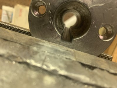
If you welded on one side causing it to bend, it was the uneven heat that expanded that area causing it to change shape.

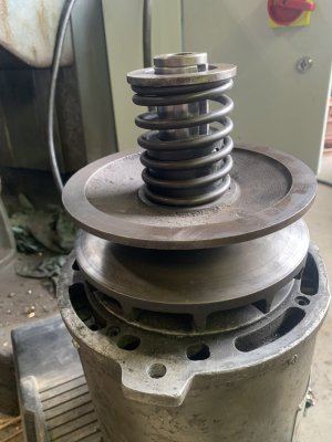
Create an easy way to measure it, maybe placing in a lathe gripped by the flange.

With a torch, apply heat opposite side of where you worked and see if you can get it to move back.

If it moves some, then you can carefully repeat as needed to get it to run true.

Sent from my SM-G781V using Tapatalk
 
Welllll I broke it real good. Long story but it’s toast. I’ve ordered 1045 steel and will be making a new one. I don’t have a means for the inside keyway. I’m thinking either a tolerance fit or slip with green loctite. I can put a set screw in at the base where the lower sheath goes also. Should I go a tolerance fit or will green loctite be enough. It will be retained by a bolt in the end of the motor shaft. I’ll attach a picture for reference.
 

Attachments

  • IMG_2301.jpeg
    IMG_2301.jpeg
    263.1 KB · Views: 21
Dang. I guess it's too late now, but I would have tried to true the faces to the bore on the lathe. It does not appear that the flange thickness is critical and function would not suffer from the reduction in dimension needed to true the part.

Sometimes, you just can't make ice cream out of poop, no matter how hard you whip it. Re-making the part seems easy enough, but that's a looong keyway to broach, go easy on it.
 
I’ve made some progress. IMG_2363.jpeg

That was a lot of passes. I finished with polishing with all the stages of sandpaper. I’ve started drilling the center out now. The motor shaft is 0.944”. I’m trying to decide if it should be a slip fit with green loctite and a set screw (or two). Or a interference fit. I could press it on.

I’m a little scared of a interference fit. I’m afraid I’ll mess up some how. Does anybody have any recommendations? If it was a interference fit what interference should I be going for? The piece is about 5.5 inches long.

I’m drilling up in stages. I’m at 5/8 now. I can only go about 3/4 off the way through so I will have to flip it around on the 4 jaw to finish. I plan on getting a s&d 7/8” to drill it. That would put it at 0.875”.

Edit: if I can find a 15/16 that would put me really close. I don’t know if it would be too close though

My second question topic is how do I get to finish diameter? I ordered a long boring bar. The plan is to at least true it up. Im assuminga 1/2” boring bar at that length will have a bit of flex. I don’t know if it will even cut well. Should I use the boring bar to completion or use a reamer? If I use a reamer I will probably have to use the drill press to run it through because the lathe doesn’t have the travel.

Thanks for taking the time to read through my post!
 
Last edited:
Also to add. I don’t know if I stated it in this thread but it’s for a 2hp motor with a vfd soft start. This is part of the reeves drive. It is retained to the motor with a bolt on the end. Just trying to find a way for it to effectively transfer torque.
 
All I have left to do is cut the external keyway. Drill and tap some holes for set screws to replace the internal keyway and drill the holes for the bottom pulley to bolt it.

I ended up drilling to 15/16” then bored with a final target size of .944. This close of a drill bit didn’t leave much room for boring and the hole isn’t 100% concentric but it fits!

I’m thinking I’ll see where set screws can fit. Ideally I’d like to do three but I think only two will fit since the bottom pulley is bolted to the shaft thing I won’t be able to put a set screw in that location. Also the motor shaft doesn’t go all the way to the end either. I will also be using sleeve retaining loctite on install.
 

Attachments

  • IMG_2378.jpeg
    IMG_2378.jpeg
    226.4 KB · Views: 4
  • IMG_2377.jpeg
    IMG_2377.jpeg
    239.3 KB · Views: 4
Well. I decided I’m already a bunch of hours in. Let’s set how filling the keyway goes. I can tell you it’s not fun! My files weren’t the best. I used a round to rough out. A square to get the profile and the edge of a mill file for the rest. To be honest the mill file worked great.

Boy are my hands tired though! I’m glad I was able to do it this way. The set screws would probably work but this is how it was made to work originally.

As far as broaching goes i had a couple concerns. I was afraid it might swell the metal since the od is at dimension. I also couldn’t find one that could do this length at the specified size.
 

Attachments

  • IMG_2378.jpeg
    IMG_2378.jpeg
    226.4 KB · Views: 8
  • IMG_2381.jpeg
    IMG_2381.jpeg
    240.4 KB · Views: 8
  • IMG_2382.jpeg
    IMG_2382.jpeg
    251.2 KB · Views: 8
That’s all done now! IMG_2413.jpeg

Just need to figure out how to install it. Multiple people have told me to drill 10-24 screw holes like a Bridgeport has but I feel like there’s not much room for them.
IMG_2415.jpegIMG_2343.jpeg

It’s hard to tell but there’s not much meat for threads. I’m sure it’s doable though.

It leaves me wondering how they installed it at the factory?

Here’s a picture of the top of the mill.
IMG_2418.jpeg
 

Attachments

  • IMG_2414.jpeg
    IMG_2414.jpeg
    222.1 KB · Views: 2
I was advised to install the pulley parts in the mill and then install the motor into the pulley vs installing the pulley on the motor and installing. That would make it a bit easier as you don’t have to fold the pulley onto the belt.
 
Back
Top