My Logan 12x24 lathe project

110--Good post. Sure like the kill switch idea.

Renn--Do run a separate ground (green). In addition to 110's info your motor plate shows that switching only the red & black leads reverses the motor. Once disconnected, you can check the switch using a multi/ohm meter so you are certain what gets connected to what, and when. Double check your work and post photos, here, before smoke testing it, if you'd like. When tested, if the switch throw isn't intuitive, reverse red and black connections.

The fact that my lathe (which has been converted to 220v 1-phase) has had its switch replaced may be a simple coincidence because it seems that your old switch should be usable, if connected properly. You may prove this with a search. Never had to deal with 3-phase til now. My mill has a static phase converter so I haven't been concerned about the differences.
 
You can't use this plug and wiring, you need hot-hot-ground (Red-black-green) a NEMA 6 or L6 (twist lock) and a fused safety disconnect switch to shot the power down . This 2 hp motor need 10A at full load under 230V so you can use a 20A plug (L6/6-20) with 12G wires (14G minimum)

This is a dedicated circuit for the lathe but if like me you want to use that plug for other tools like a plasma cutter or a MIG welder you need at least a 50A receptacle like a 6-50R with 10G wiring (12G minimum) control by a fused safety switch (twin 25A time-delay fuse or twin 30A normal fuse) and you install a 2hp 230V single phases starter on the lathe.

NEVER USE THE WHITE NEUTRAL WIRE and ground the motor body to the machine with a isolate green wire.

http://upload.wikimedia.org/wikipedia/commons/0/0d/NEMA_simplified_pins.svg
 
Last edited:
You can't use this plug and wiring, you need hot-hot-ground (Red-black-green) a NEMA 6 or L6 (twist lock) and a fused safety disconnect switch to shot the power down . This 2 hp motor need 10A at full load under 230V so you can use a 20A plug (L6/6-20) with 12G wires (14G minimum)

This is a dedicated circuit for the lathe but if like me you want to use that plug for other tools like a plasma cutter or a MIG welder you need at least a 50A receptacle like a 6-50R with 10G wiring (12G minimum) control by a fused safety switch (twin 25A time-delay fuse or twin 30A normal fuse) and you install a 2hp 230V single phases starter on the lathe.

NEVER USE THE WHITE NEUTRAL WIRE and ground the motor body to the machine with a isolate green wire.

http://upload.wikimedia.org/wikipedia/commons/0/0d/NEMA_simplified_pins.svg


Ok, several questions...

Why do I need a separate fused disconnect? The breaker panel is less than 10ft from the lathe and the circuit is breaker protected. Seems like somewhat overkill...

Why would I need a starter on a capacitor start/run motor?

Is there some reason that for my own use I couldn't just switch the neutral wire in the breaker panel to ground and use what I have. There isn't going to be a dryer hooked up to it (house is all natural gas these days).

I'd kind of rather not run another circuit given the expense to put a drop out in the middle of the garage floor. The original wiring is properly sized for what I'm doing (a dryer draws a LOT more amperage continuously than a 2hp motor), just needs the neutral/ground situation fixed.

What I'm really stuck on is wiring the drum switch to the motor. Since none of the wiring terminology matches between the switch and the motor or between the info I've found doing searches. Nice of Marathon to just use the wire colors rather than what appears to be a standard notation (T1,T2, etc). It appears I have a pretty standard switch and a not uncommon motor, it's just not marked in a way my non-electrician brain is finding difficult.
 
I am not a licensed electrician and so I am not specifying anything, only informally commenting. The NEC (National Electrical Code) is primarily designed to protect electrical systems from fire and personal safety hazards. As an aside, I don't always agree with the code, but most all of it is well intended and important - lately the code has been corrupted with some component manufacturers installing rules about spark proof receptacles in bedrooms (most of us do not have an explosive atmosphere in the bedroom, er-well best left at that!).

A branch line circuit breaker is not intended nor to be used as a switch. Even though your breaker is "within sight" of the machine, it is not the best way to serve as an equipment disconnect. Likewise the neutral wire is not a "ground" wire. Any unbalance of the load will place current in this "neutral" wire. The NEC requires an "equipment grounding conductor" that is independent of the neutral wire. You will notice that newer electric dryer supply wires and the plugs and short dryer chords have four wires. New electric dryer installations are following the intent of the code.

Since your motor is single phase you do not need a "starter" in the conventional dialogue. Motor starters in the sense we are discussing are for (mostly) larger three phase motors. These starters use "heaters" to protect each phase of the circuit and most often (not always) use a relay type connection method. That is, there is a solenoid that when the starter is engaged by a separate push button the switch magnetically pulls closed completing the circuit through the "heaters" to the motor. "Heaters" used in this sense are just a form of fuse, just a matter of vernacular. Three phase can have a balance problem which is not applicable to single phase. You may have heard some maintenance folks mention "it dropped a phase". This means one phase was lost or went to ground and caused a problem (often a big problem).

Hope this addresses your situation. A light duty "safety switch" is not an expensive piece of equipment. I would say that one up to thirty amps would be about $20 and I bought an old heavy item (much better construction than today's light stuff) for $5. Of course, that was luck, it is a "Bulldog" brand and looks like it was designed to handle being hit with a 30-06 slug.

You can put a switch box in place of the present dryer plug and run some metallic cable to the drum switch. Metallic cable is available in short lengths and you can get short lengths of wire to run through it which will reduce your out of pocket expenses. You can run a separate green wire back to the supply panel just to be safe-that might not make an inspector happy but it's there. By the way, I didn't just say that, ignore all of this dialogue. As to the "equipment ground" do not "daisy chain" your ground wire from the safety switch to the motor and the drum switch.

I might have a circuit diagram for your drum switch. Give us the data on the switch, brand, rating, model, etc. and I may have a wiring diagram. Single phase motors have a starting circuit and that is the only problem that has to be determined. GCM
 
You can't use the white wire for ground! It's again the code! Only cable can't be "recolored" with tape or paint. All the last statement of 110actane is 100% wright! The mod I suggest you is for using other tools like welder or plasma cutter from that plug but if you want a dedicated plug for the lathe just add a 14g green isolated wire in the conduit (or change the wall wiring) disconnect the white wire from the panel and use only the 220V power (red/black/green) and a NEMA L6/6-15 3 wires receptacle.

A more complicate way to get 120V/240V using all four wires from the same receptacle to power a working light or a cutting oil pump (120V) can be achieved using a simple NEMA L14/14-20 receptacle. Of course you need to wire correctly each components from a aux power distribution box.

_______Why you need a starter or a disconnect switch______

One side of the split phases is constantly powered on a single phases motor wen it's connected to a drum switch, you need to shot down the power to it, using your breaker box is not legal ....A starter can be use with heaters matching your motor size and you can even add external emergency switch.
OR you can just use a cheap fused disconnected switch with the appropriated fuse for your load like 110octane suggest you.

The choice is yours....Each way are safe and legal ^_^

Now you need to find what is you starting winding and running winding on this motor, you can reed on the case "reverse red and black" (5 and 8) open the motor terminal box and take a picture.
 
No resolution on the motor wiring as yet, a friend of a friend who is a licensed electrician here locally is going to look at it.

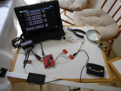
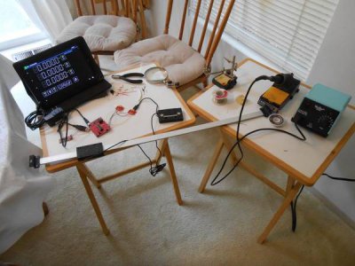
In other news though I built the first of my Android DRO controllers yesterday. It communicates with my laptop just fine and the tablet connects to the bluetooth but having an issue uploading the code to the controller. Yuriy is having a look at it, I'm guessing I'm mistyping or not understanding the syntax for the program that flashes the code into the controller. Once I get it working on the bench I'll put it in an enclosure.

A couple pics...

DSCN8852_zpsc9112fe2.jpg

DSCN8854_zpsa244abc3.jpg
 
Wow, that's all way beyond me. I'd just have to buy one, or ask one of my tweek friends to do it. :man:
 
Wow, that's all way beyond me. I'd just have to buy one, or ask one of my tweek friends to do it. :man:


Thanks Greg...

Building them isn't really all that difficult, maybe 10 solder connections and Yuriy did a great job on the assembly guide. I'm just having problems uploading the code into the microcontroller at the moment. I'll get that figured out though.

I'm just cheap, the parts to build a pair of these with all the scales for 2 axes on the lathe and 3 axes on the mill was only ~$250 vs ~$450 for each machine for the cheaper Chinese dedicated DRO's. The other nice thing about these is that if new features are added, I just update the app on my tablet. Pretty cool.
 
Serial # 67871 would put it somewhere in 1955. You can find the list here:


That's a link to the data base at the Logan user group. It's moderated by Scott Logan. You may have to join the group to view the page...

Chuck

Thanks! I'm a member there as well - predates joining here actually - and that's where I checked my S/N - and entered it into the database...


It looked that way in 1942 as well. :tiphat:


And in 1961 when mine was built. :thumbsup:

Mine was broken at some point and one of the PO's made one on the cheap. Since it's fully functional I just cleaned it up a bit (after I checked on the price for a new one from Logan). I'll keep an eye on Ebay for an OEM one in decent condition.[/QUOTE]


Mine look pretty similar - ~1954 - 1955...

Well, I've figured out *part* of the problems with the tailstock of my "new" lathe... The Morse taper for the drill chuck's arbor is jammed in there, but good...

This may take a heat & beat treatment to get things separated.

This still leaves the question as to why the screw to advance & retract the quill is so tight - almost as if the old boy who "fixed" it used a square threaded rod instead of ACME threads... or the reverse...

I got some WD-40 into the threads, but I still had to chuck the quill up in a vise and turn the screw using Channel-Locks to get the blasted screw out - tight is too gentle a word to describe how this thing resisted turning...

Add this to the need to mill up a new clamping block to go under the ways - the factory casting broke into 3 pieces, and while I was able to glue them back together with JB Weld, that was just to get the dimensions...

On the electrical front, I got the idler motor wired up to the rotary phase converter - now, I just need a cooler day to connect up the single phase breaker to the panel box...

So, I made a little progress this weekend, despite the hot weather...

Eric
 
Last edited by a moderator:
Back
Top