My Logan 12x24 lathe project

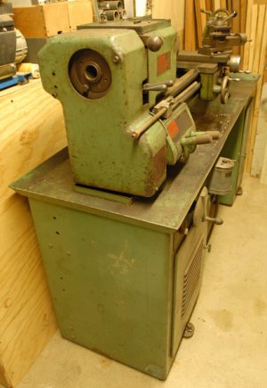
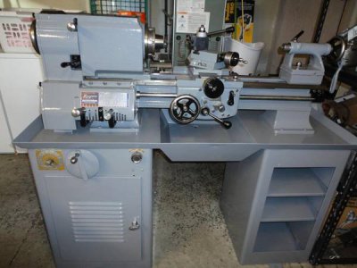
Annnnnnnd it's all together (mechanically)...

Still need to wire it up as I posted above (anyone wire up the stock Logan Fwd/Off/Rev switch to a 220 single phase motor?) and then it's time to start tossing chips around!

Next I'll be building my DRO controller(s) and mounting the scales for the Android DRO.

A pic of it all together and painted...

DSC04307_zps9c70f80f.jpg
 
Wow, looks amazing! Great job and fast too. Kinda sad to see it come to an end, it's been a fun project to watch, followed it all the way.
 
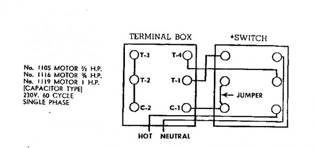
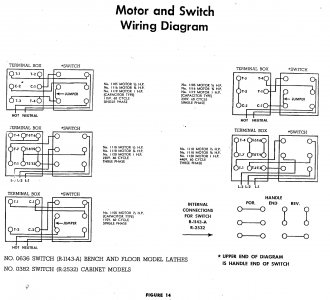
So since the lathe is almost together... anyone have a clue how to wire up the stock Logan forward/reverse switch for a 220V 1 Phase motor? I have the factory book and the diagram in it isn't particularly clear.

Sorry for the late answer...Since a picture have the value of thousand words....Check this up:


Logan s.jpg

The terminal box is on the motor, top of diagram is the selector side, maybe Ezduzit can came back with a picture of the switch with indication since his lathe got a 220V single phase motor like yours.


Logan switch.jpg Logan s.jpg
 
The switch had been changed out to a different type on my lathe, along with the motor. It shows up in this photo. And it needs to be relocated or a guard installed to prevent accidental actuation.

mill-9_zps14aba78f.jpg
 
Looks like a "standard" Dayton drum switch, or an equivalent competitor model. Looks like it has an nomenclature plate on the switch. If you can quote the information someone will have a wiring schematic. There are lots of circuit wiring diagrams and other data for these switches available on line.
Good Luck, Geoff Morgan
 
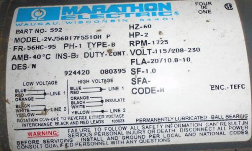
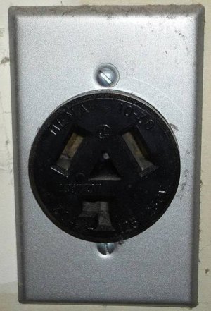
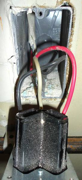
Thanks guys for attempting to get me going on the wiring. I have the factory manual with the switch wiring, problem is I just don't know what's what. I'm hooking this to a 3 wire dryer outlet (maybe that's part of the problem) which has a hot, neutral, and ground. I don't see anyplace on here to hook the ground or is that just motor case to ground on the plug?

Here's a pic of the diagram on the motor. I'm hooking it up 208/230.

DSC04317_zps601810ad.jpg

And here is a pic of the wiring to the back of the dryer plug...

DSC04318_zps3c081114.jpg

DSC04319_zps96e43a42.jpg

So what goes where??
 
Just as a suggestion; you know the standard disclaimer here, I'm not directing or telling you, just discussing this for entertainment purposes wherein I claim no skill or knowledge. You may want to replace the plug with a manual "safety switch". These are a box with a handle on the side that can be obtained for outfitting with fuses. Looks like you would something in the neighborhood of 15 amp slow blow fuses. No. 10 AWG wire should handle up to 20 amps. Get the THW or better rated insulated wire. You should install the safety switch within safe reach of the machine. This gives you a way to disconnect the lathe rapidly should an electrical problem develop. The fuses offer some extra protection.

Remember in single phase conventional home circuitry, both the red and black wire are "hot". A meter should read about 110 volts between each one and the white "neutral" wire and about 220 volts between the red and black wire. In the newer codes, there is the requirement of a separate full sized ground which runs parallel to the "neutral" (white) wire. If you want to meet any up to date and local codes you will need a qualified electrician to guide you or do the work. There is an excellent little book "Wiring Simplified" by H.P. Richter and his successors. Most big box stores have this little jewel of a book in the electrical section at a reasonable price.

Be safe, make sure the power is off, even if you THINK it is off: if you have doubts about any connections or routing, etc. stop there and don't do it. Hope this kicks things off. Geoff
 
Back
Top